Hydrophobic melt-blown fabric preparation method

A melt-blown fabric and hydrophobic technology, which is applied in the direction of melt spinning, non-woven fabrics, and clustering of newly extruded filaments. The effect of loft and air permeability

Inactive Publication Date: 2020-09-11
烟台舒朗医疗科技有限公司
View PDF8 Cites 8 Cited by
  • Summary
  • Abstract
  • Description
  • Claims
  • Application Information

AI Technical Summary

Problems solved by technology

But the device can not ch

Method used


Image

  • Hydrophobic melt-blown fabric preparation method
  • Hydrophobic melt-blown fabric preparation method
  • Hydrophobic melt-blown fabric preparation method

Examples


specific Embodiment approach 1

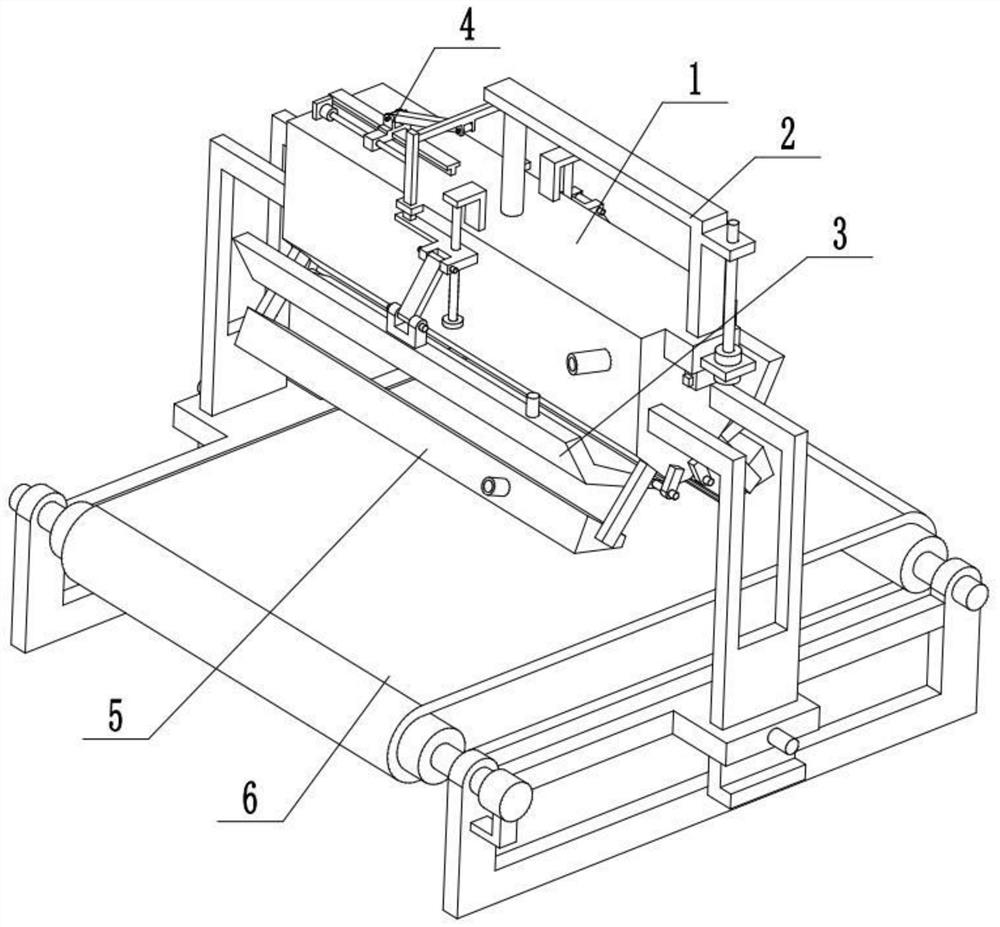
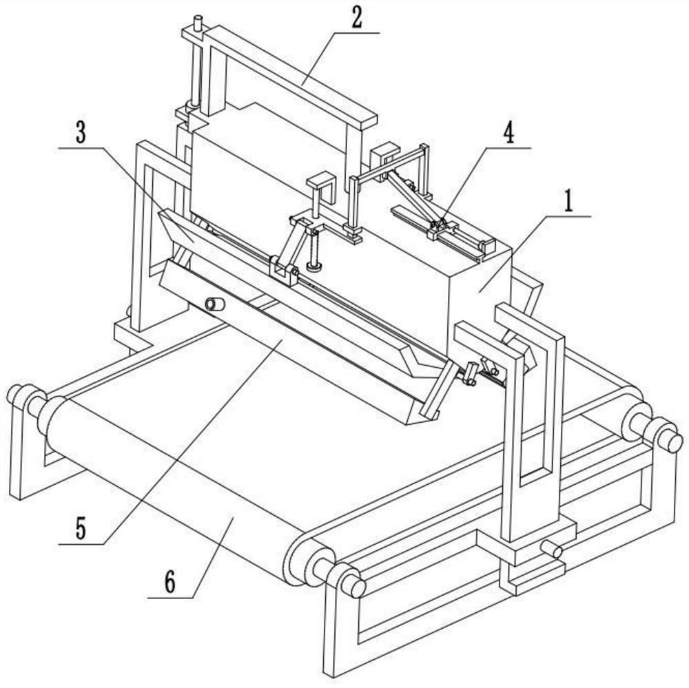
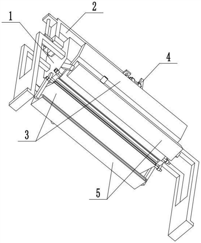
[0033] Combine below Figure 1-9 To illustrate this embodiment, a method for preparing a hydrophobic melt-blown cloth comprises the following steps:

[0034] Step 1, stock solution addition: add raw material solution, and the raw material solution is sprayed out;

[0035] Step 2, drafting: high-temperature airflow drafts the raw material solution to form ultrafine fibers;

[0036] Step 3. Cooling: the ejected ultrafine fibers are bonded under the action of self-bonding, and the cooling airflow makes the ejected ultrafine fibers form a melt-blown cloth;

[0037] Step 4, transportation: the melt blown cloth is transported to the next station;

[0038] Step 5. Adjust the angle: adjust the angle of the high-temperature airflow to obtain a melt-blown cloth with good fiber shape;

[0039] The method for preparing hydrophobic melt-blown cloth also relates to a preparation device for hydrophobic melt-blown cloth;

[0040]The hydrophobic melt-blown cloth preparation device includes...

specific Embodiment approach 2

[0042] Combine below Figure 1-9 To illustrate this embodiment, the meltblown die head assembly 1 includes a nozzle 1-1, a liquid inlet pipe 1-2 with a control valve, a side carriage 1-3, a sliding sleeve 1-4, a T-shaped bar 1- 5. The side fixing sleeve 1-6 and the injection port 1-7; the liquid inlet pipe 1-2 is fixedly connected to and communicated with the nozzle 1-1, and the two ends of the nozzle 1-1 are respectively fixedly connected to a side carriage 1-3 , the two side sliding frames 1-3 are all connected with the receiving device 6, the sliding sleeve 1-4 and the T-shaped bar 1-5 are fixedly connected to the front and rear ends of the liquid inlet pipe 1-2 respectively, and the two side fixing sleeves 1 -6 is symmetrically and fixedly connected to the left and right ends of the nozzle 1-1, and the extruding device 2 is connected with the nozzle 1-1 to cooperate with the high-temperature air flow generator assembly 3, which is symmetrically arranged at the lower end of...

specific Embodiment approach 3

[0044] Combine below Figure 1-9 To illustrate this embodiment, the extrusion discharge device 2 includes a first motor 2-1, a screw 2-2, an L-shaped frame 2-3, a telescopic rod 2-4 and an extrusion plate 2-5; the first motor 2-1 is fixed on the nozzle 1-1 through the motor frame, the output shaft of the first motor 2-1 is connected to the screw rod 2-2 through a coupling, and the front end of the L-shaped frame 2-3 is connected to the screw rod 2-2 through thread fit. 2, the two ends of the telescopic rod 2-4 are respectively fixedly connected to the L-shaped frame 2-3 and the extruding plate 2-5, and the telescopic rod 2-4 is sealed and slidably connected to the upper end of the nozzle 1-1, and the extruding plate 2- 5 is connected by sliding fit inside the nozzle 1-1, and the liquid inlet pipe 1-2 is located at the lower end of the extruding plate 2-5. The first motor 2-1 starts to drive the extrusion plate 2-5 to move downward through the screw rod 2-2, L-shaped frame 2-3...


PUM


Abstract

The invention relates to a technical field of melt-blown fabric production, and more specifically, discloses a hydrophobic melt-blown fabric preparation method. The hydrophobic melt-blown fabric preparation method comprises the following steps: step 1, stock solution adding: adding raw material solution, and spraying out the raw material solution; step 2, drafting: drafting the raw material solution with high temperature to form a superfine fiber; step 3, cooling: adhering the superfine fiber sprayed out through own adhesive action, making the superfine fiber sprayed out form a melt-blown fabric through a cooling air flow; step 4, transporting: transporting the melt-blown fabric to next work station; step 5, angle adjustment: adjusting angle of the high temperature air flow, and obtainingthe melt-blown fabric with good fiber morphology. In the hydrophobic melt-blown fabric preparation method above, a hydrophobic melt-blown fabric preparation apparatus is also related; the hydrophobicmelt-blown fabric preparation apparatus comprises a melt-blown die head component, an extrusion discharging apparatus, a high temperature air flow generator component, an angle adjustment apparatus, acooling air flow generator and a receiving apparatus, wherein the belt-blown die head component is arranged on the receiving apparatus.

Description

technical field [0001] The invention relates to the technical field of melt-blown cloth production, more specifically, a method for preparing hydrophobic melt-blown cloth. Background technique [0002] The patent number is CN201410524317.5, a method for preparing fluffy melt-blown cloth, the invention relates to a method for preparing fluffy melt-blown cloth; raw materials are heated, melted and extruded through a screw extruder, filtered through a filter, and then transported through a pipeline The melt is measured by the metering pump, and then sent to the die head, and fine fibers are formed under the drafting action of high-speed hot air. Under the action of negative pressure, the fiber is laid on the web forming table to form a non-woven fabric; it solves the problems of hard hand feeling of the cloth surface, poor fluffy performance of the fiber, and thin cloth surface thickness; it is fluffy, tough and soft to the touch. But this device can't change the jet angle of ...

Claims


Application Information

Patent Timeline
IPC IPC(8): D04H1/56D01D5/098D01D7/00
CPCD01D5/0985D01D7/00D04H1/56
Inventor 曹聪
Owner 烟台舒朗医疗科技有限公司
Why Eureka
Try Eureka