Wavefront restoration method and system based on diffractive optical neural network

A neural network and diffractive optics technology, applied in the field of wavefront restoration methods and systems based on diffractive optical neural networks, can solve problems such as slow speed, high energy consumption, loss of phase information, etc. Simplified effect

Active Publication Date: 2020-09-11
INST OF SOFTWARE - CHINESE ACAD OF SCI
View PDF3 Cites 3 Cited by
  • Summary
  • Abstract
  • Description
  • Claims
  • Application Information

AI Technical Summary

Problems solved by technology

[0005] Since the existing wavefront restoration requires photoelectric conversion (i.e. photoelectric detection) first, and then the data is input into the elec

Method used


Image

  • Wavefront restoration method and system based on diffractive optical neural network
  • Wavefront restoration method and system based on diffractive optical neural network
  • Wavefront restoration method and system based on diffractive optical neural network

Examples


Embodiment 1

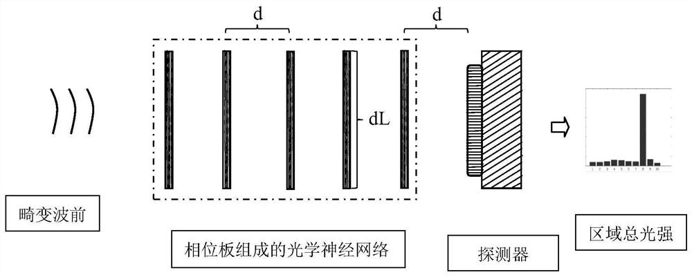
[0033] The system diagram of embodiment 1 is as follows figure 1 As shown, the attached figure 1 Describe the detailed implementation process of the technical solution of Embodiment 1.

[0034] First, the wavefront W is decomposed into Zernike polynomials, and within the first 10 Zernikes, the third-order Zernikes are randomly selected, given by Generate a mixed wavefront, which forms a data pair with the corresponding coefficients, and repeat the above process to generate a data set consisting of about 20,000 wavefront-coefficient data pairs.

[0035] Secondly, under a deep learning framework such as Tensorflow, construct an optical neural network model, set the size and interval of the phase plate, and use the phase distribution of the phase plate as a parameter to train the data set. The phase in the data set is used as the input of the neural network to obtain the corresponding output, and the loss function is used to compare the output with the N-order Zernike coeffici...

Embodiment 2

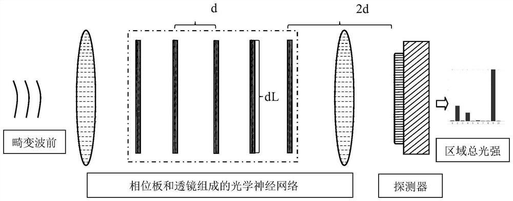
[0038] The system diagram of embodiment 2 is as follows figure 2 As shown, the attached figure 2 Describe the detailed implementation process of the technical solution of Embodiment 2.

[0039] First, within the first 10 Zernikes, the third-order Zernikes are randomly selected to generate a mixed wavefront, thereby generating a data set consisting of about 20,000 wavefront-coefficient data pairs.

[0040] In this example, in order to overcome the situation that the energy distribution may exceed the size of the phase plate in the process of light wave propagation that may occur in multi-order phases, focusing mirrors are placed front and back to gather light waves.

[0041] Secondly, under a deep learning framework such as Tensorflow, construct an optical neural network model, train the data set, and finally obtain the two-dimensional phase distribution of each phase plate, which is converted into the thickness of the phase plate according to the refractive index.

[0042]...


PUM


Abstract

The invention discloses a wavefront restoration method and system based on a diffractive optical neural network. The method comprises the following steps: 1) selecting or constructing a data set composed of wavefront-coefficient data pairs containing first N orders of Zernike; 2) constructing an optical neural network model, and fitting the data set to obtain two-dimensional phase distribution ofeach phase modulation plate in the model; determining the thickness of the corresponding phase modulation plate according to the two-dimensional phase distribution of each phase modulation plate, thewavelength of the light wave to be measured, and the refractive index and transmittance of the required phase modulation plate; and (3) manufacturing corresponding phase modulation plates according tothe thicknesses of the phase modulation plates determined in the step (2), respectively placing the phase modulation plates behind the wavefront to be measured according to the positions in the optical neural network model, modulating the complex amplitude of the optical wave, then detecting the light intensity distribution after passing through the phase modulation plates, and carrying out wavefront restoration according to the light intensity distribution. Photoelectric conversion and dependence on an electronic computer are avoided, and the method has the advantages of being low in energyconsumption, high in speed and the like.

Description

technical field [0001] The invention relates to a wavefront restoration method, in particular to a wavefront restoration method and system based on a diffractive optical neural network. Background technique [0002] Adaptive optics (AO) aims to correct the wavefront that causes the distortion of the optical system (the following "wavefront" and "phase" are not distinguished), thereby improving the imaging capability of the optical system, and is widely used in laser systems, astronomical observations, and medical treatment imaging and other fields. If the technical route with wavefront detection is adopted, it is necessary to detect the distorted wavefront first, and then correct it. [0003] Since the phase of the light wave cannot be detected directly, an optical detection system is usually constructed to detect the light intensity, and then a certain wavefront restoration algorithm is used to invert the wavefront. There are currently two technical routes for the wavefro...

Claims


Application Information

Patent Timeline
IPC IPC(8): G06N3/10G06N3/067G06N3/08G01J9/00
CPCG06N3/10G06N3/0675G06N3/08G01J9/00
Inventor 刘贺吕品徐帆江李程
Owner INST OF SOFTWARE - CHINESE ACAD OF SCI
Why Eureka
Try Eureka