Radar cross section test system and radar cross section detection method

A radar cross-section and testing system technology, applied in the field of radar cross-section testing, can solve problems such as test result deviation, large reflection, and deteriorating environmental stability, and achieve improved efficiency and accuracy, high detection accuracy, and elimination of environmental fluctuations Effect

Pending Publication Date: 2020-09-15
FRAGRANT MOUNTAIN MICROWAVE CO LTD
View PDF0 Cites 9 Cited by
  • Summary
  • Abstract
  • Description
  • Claims
  • Application Information

AI Technical Summary

Problems solved by technology

[0004] The existing units that can provide radar cross-section testing systems are mainly scientific research institutes and universities, which are mostly used for radar cross-section testing of military products. There is no mature commercial product of the microwave radar cross-section test system in the millimeter wave band. The radar cross-section test system requires the servo mechanism to carry the DUT to rotate and move along a certain trajectory in three-dimensional space. The traditional turntable and scanning frame cannot achieve any azimuth angle. , Arbitrary pitch angle and arbitrary curve movement. In addition, the drive part of the traditional servo mechanism cannot be covered with absorbing materials, and its reflection is very large. The vector subtraction of the test results fails, which brings deviations to the test results. The validity of the calibration data of the traditional radar cross section test system can only be maintained for a few minutes. It will change the darkroom environment, deteriorate the stability of the environment, and further increase the uncertainty of the test

Method used


Image

  • Radar cross section test system and radar cross section detection method
  • Radar cross section test system and radar cross section detection method
  • Radar cross section test system and radar cross section detection method

Examples


Embodiment Construction

[0037] Embodiments of the present invention are described in detail below, examples of which are shown in the drawings, wherein the same or similar reference numerals designate the same or similar elements or elements having the same or similar functions throughout. The embodiments described below by referring to the figures are exemplary only for explaining the present invention and should not be construed as limiting the present invention.

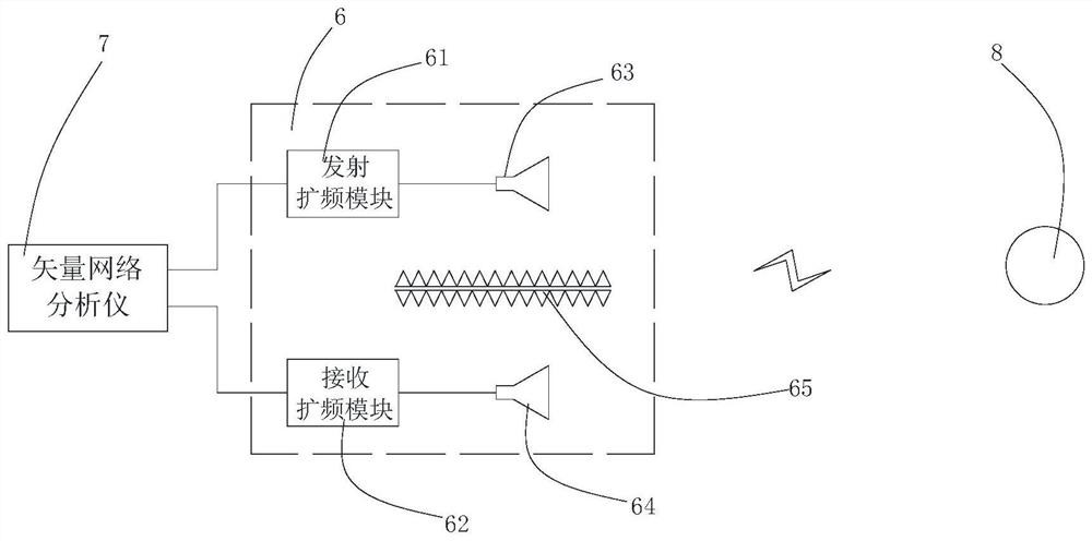
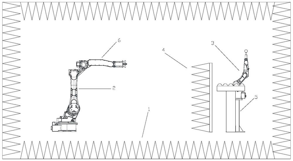
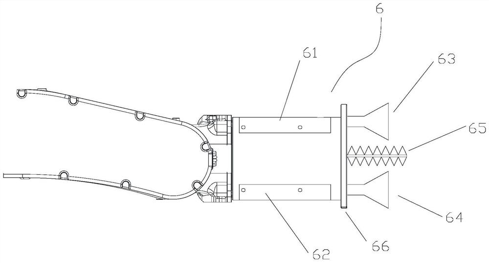
[0038] As one hand, please combine figure 1 with 2 As shown, the present invention relates to a radar cross-section test system (hereinafter referred to as “test system”), which is suitable for detecting the radar cross-section data of the test object 8 . The testing system includes a darkroom 1 , and a detection robot 2 , a vector network analyzer 7 , a radio frequency transceiver 6 , a DUT robot 3 , a tray 5 , and a wave-absorbing baffle 4 all arranged in the darkroom 1 .

[0039] The detection robot 2 is arranged at one end in the d...


PUM


Abstract

The invention relates to a radar cross section test system and a detection method. The test system comprises a darkroom, and a detection robot, a vector network analyzer, a radio frequency transceiving device, a to-be-tested piece robot, a tray and wave-absorbing baffle plates which are arranged in the darkroom, wherein the radio frequency transceiving device is electrically connected with the vector network analyzer and is driven by the detection robot to move to detect a to-be-detected piece, the to-be-detected piece robot is arranged on the tray and can grab the to-be-detected piece placedin the tray for detection, and the wave-absorbing baffle plates are distributed between the detection robot and the to-be-detected piece robot. By adopting the test system, full-automatic test can becarried out on the to-be-tested piece, feeding and discharging of the to-be-tested pieces are completely and automatically controlled, manual operation is not needed, extra interference cannot be brought to the dark room environment, and the efficiency and the accuracy are improved.

Description

technical field [0001] The invention relates to the field of radar scattering cross section testing, in particular to a radar scattering cross section testing system and a radar scattering cross section testing method thereof. Background technique [0002] RCS (Radar Cross section, radar cross section) test system is divided into outdoor test field, indoor test field, parabolic compression field and other types according to the test environment. Filtering and other technologies have greatly improved the signal-to-noise ratio and resolution system, and can realize two-dimensional and three-dimensional imaging of target scattering points, and can carry out on-site testing of aircraft, missiles and other targets, and realize target imaging and scattering diagnosis. [0003] At present, with the increase of the application frequency band, communication and radar detection have entered the millimeter wave and submillimeter wave bands, and the accompanying various module designs a...

Claims


Application Information

Patent Timeline
Patent Type & Authority Applications(China)
IPC IPC(8): G01R29/10
CPCG01R29/105
Inventor 卜景鹏东君伟乔梁马向华
Owner FRAGRANT MOUNTAIN MICROWAVE CO LTD
Why Eureka
Try Eureka