Powder for coating an etch chamber

A powder and coating technology, applied in the coating field of semiconductor etching chamber, can solve the problems of increasing corrosion resistance of semiconductor etching chamber coating and other problems

Active Publication Date: 2020-09-15
SAINT GOBAIN CENT DE RES & DEVS & DETUD EUROEN
View PDF14 Cites 2 Cited by
  • Summary
  • Abstract
  • Description
  • Claims
  • Application Information

AI Technical Summary

Problems solved by technology

[0015] However, there remains a need for semiconductor etch chamber coatings with increased corrosion resistance and reduced defect counts

Method used


Image

  • Powder for coating an etch chamber
  • Powder for coating an etch chamber
  • Powder for coating an etch chamber

Examples


Embodiment

[0164] The following examples are provided by way of illustration, not limitation of the scope of the invention.

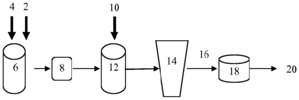
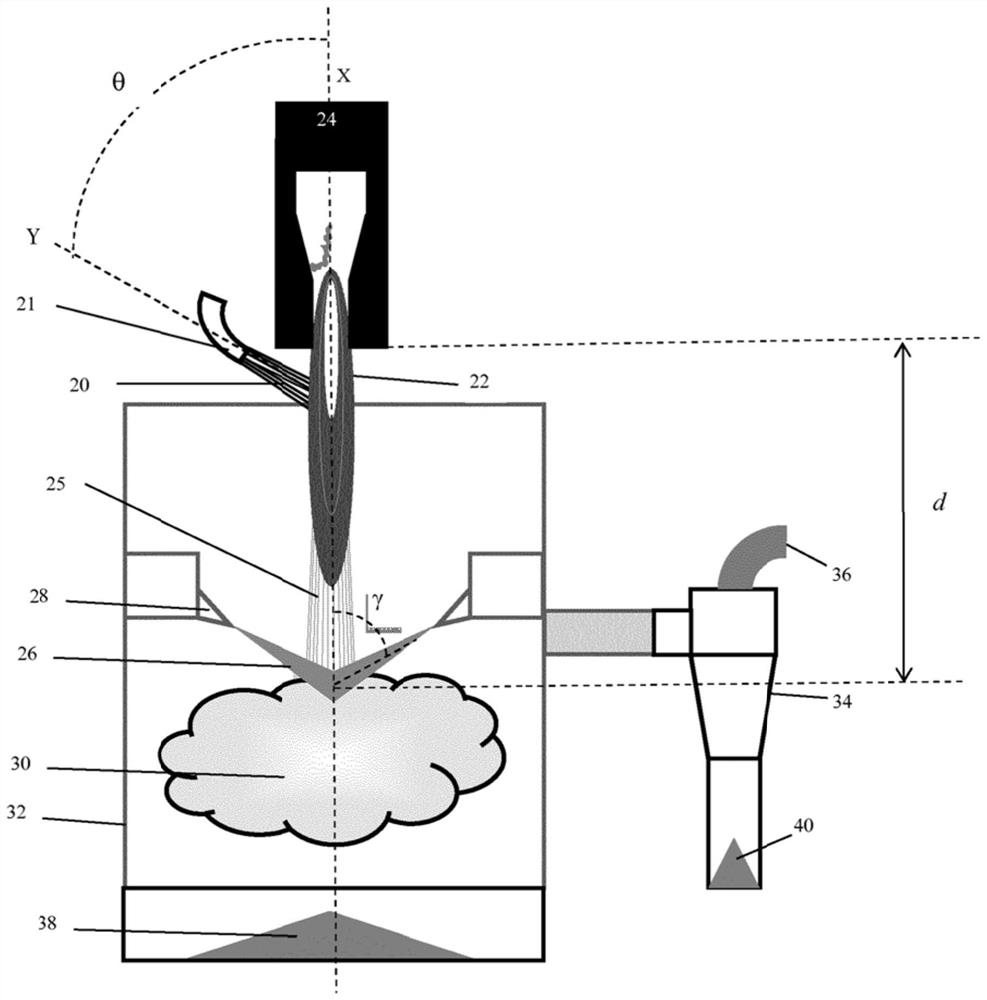
[0165] Feed powder H1, feed powder I1 (comparative example) and feed powder C1 (comparative example) are used in WO2014 / 083544 figure 2 The plasma torch shown in the similar plasma torch has a median particle size D measured with a Horiba laser particle analyzer. 50 1.2 micron pure Y 2 o 3 Powder (Y with a chemical purity of 99.999% 2 o 3 ) made of.

[0166] In step a), by applying PVA (polyvinyl alcohol) adhesive 2 (see figure 1 ) was added to deionized water 4 to prepare the binder mixture. The binder mixture is then filtered through a 5 μm filter 8 . Yttrium oxide powder 10 is mixed into the filtered binder mixture to form slip 12 . The slip was made to contain 55% by mass of yttrium oxide and 0.55% of PVA, the balance to 100% being deionized water. Mix the slip vigorously using a high shear speed mixer.

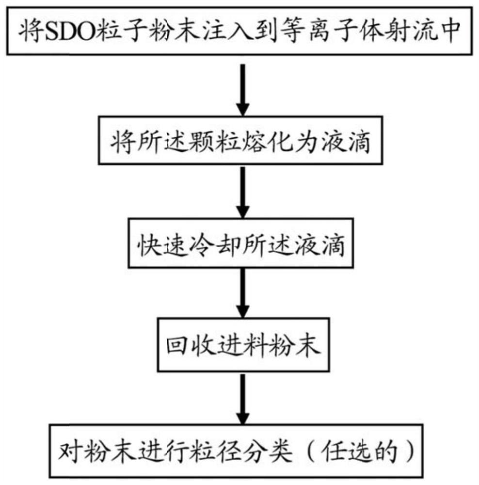
[0167] The particles G3 are subsequently ob...


PUM


Abstract

Particle powder, a number greater than 95% of the particles having a circularity greater than or equal to 0.85, the powder containing more than 99.8% of a rare earth oxide and / or a hafnium oxide and / or an aluminium oxide, as a percentage by weight on the basis of the oxides, and having: a median particle size D50 less than 15 [Mu]m, a 90th percentile of the particle sizes D90 less than 30 [Mu]m, and a size dispersion index (D90 -D10) / D10 less than 2; and a relative density greater than 90%.

Description

technical field [0001] The present invention relates to a powder suitable for deposition by plasma, a method for producing such a powder, and a coating obtained by plasma spraying said powder, more particularly to a semiconductor etching chamber coating. Background technique [0002] The interior surfaces of chambers used for processing (for example by plasma etching) semiconductors such as silicon wafers are usually protected with a ceramic coating applied by plasma spraying. The coating needs to be highly resistant to halogen-containing plasmas or highly corrosive environments. Plasma spraying requires a powder with a high flowability and a granular form that allows proper heating during the spraying process as a feed powder. More specifically, the size of the particles must be sufficient to make the particles permeable to the plasma and limit evaporation losses. [0003] For example, for the formation of larger (and porous) aggregates, more particularly sintered aggreg...

Claims


Application Information

Patent Timeline
IPC IPC(8): C01G27/02C23C4/10C04B35/10C04B35/48C04B35/50C04B35/505C01F17/206C01F17/218C01F17/224C01F17/259C01F17/34C01F17/10
CPCC01G27/02C03B1/00C04B35/10C04B35/48C04B35/50C04B35/505C23C4/10C01P2002/30C01P2002/34C01P2004/50C01P2004/51C01P2004/52C01P2004/54C01P2004/61C01P2004/62C01P2006/12C01P2006/14C01F17/32C23C4/11H01J37/32477C01F17/206
Inventor 阿兰·阿利芒霍华德·瓦拉尔
Owner SAINT GOBAIN CENT DE RES & DEVS & DETUD EUROEN
Why Eureka
Try Eureka