Shock wave robot treatment system based on structured light positioning

A treatment system and positioning system technology, applied in surgical robots, physical therapy, surgical navigation systems, etc., can solve problems such as failure to achieve treatment effects, failure to keep the gun handle stable, and impact on shock wave transmission.

Pending Publication Date: 2020-09-18
北京水木东方医用机器人技术创新中心有限公司
View PDF6 Cites 2 Cited by
  • Summary
  • Abstract
  • Description
  • Claims
  • Application Information

AI Technical Summary

Problems solved by technology

It is difficult for the doctor to hold the gun handle stably for a long time, and the continuous vibration of the shock wave gun handle during the treatment may also easily cause fatigue damage to the doctor's limbs
[0004] If a passive support manipulator is used to hold the gun handle of the shock wave device and perform fixed-point treatment on the affected part of the patient, the mobile treatment of the shock wave gun handle on the human body surface cannot be realized. Every time the doctor changes to another part during treatment, the doctor has to pull the manipulator again Once, time-consuming and labor-intensive
Moreover, holding it at a fixed position for a long time cannot keep the relative position of the gun handle and the patient's body surface stable, which will affect the effective and stable transmission of shock wave energy to the treatment site, and the ideal treatment effect cannot be achieved.

Method used


Image

  • Shock wave robot treatment system based on structured light positioning
  • Shock wave robot treatment system based on structured light positioning
  • Shock wave robot treatment system based on structured light positioning

Examples


Embodiment Construction

[0045] In order to make the purpose, technical solutions and advantages of the embodiments of the present disclosure clearer, the technical solutions in the embodiments of the present disclosure will be clearly and completely described below in conjunction with the drawings in the embodiments of the present disclosure. Obviously, the described embodiments It is a part of the embodiments of the present disclosure, but not all of them. Based on the embodiments in the present disclosure, all other embodiments obtained by persons of ordinary skill in the art without creative efforts fall within the protection scope of the present disclosure.

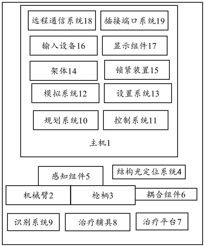
[0046] Such as Figure 1 to Figure 4 As shown, according to the embodiment of the present invention, a shock wave robot therapy system based on structured light positioning is provided, including a shock wave robot composed of a host 1 and a mechanical arm 2, a gun handle 3 and a structured light positioning system 4, wherein,

[0047] The ...


PUM


Abstract

The invention provides a shock wave robot treatment system based on structured light positioning. The shock wave robot treatment system comprises: a main machine, which comprises a planning system anda control system; a mechanical arm, which is mounted on the main machine; a gun handle, which is installed at the tail end of the mechanical arm, wherein a shock wave generating device is arranged inthe gun handle, and a gun head is arranged at the front end of the gun handle; and a structured light positioning system, which is used for acquiring and generating patient image information and determining and generating position information of the mechanical arm; wherein the planning system is used for establishing a virtual three-dimensional model of a patient according to the patient image information generated by the structured light positioning system and positioning a target treatment area of the patient on the basis of the virtual three-dimensional model to plan a treatment path; andthe control system is used for controlling the mechanical arm to move according to the planned treatment path. According to the structure provided by the invention, the treatment path can be planned on a software on the basis of information collected by the structured light system, and shock wave automatic and mobile treatment is carried out according to the planned path, so the technical problemsexisting in conventional handheld shock wave treatment and shock wave single-point treatment are solved.

Description

technical field [0001] The present invention relates to the field of shock wave therapy, and more specifically relates to a shock wave robot therapy system. Background technique [0002] Orthopedic shock wave therapy, as a treatment method with quick onset, long-lasting effect and no obvious side effects, is more and more widely used in osteoarthritis, cartilage injury, tenosynovitis, osteonecrosis diseases (lunar osteonecrosis, talus osteonecrosis, Scaphoid osteonecrosis) and other diseases. [0003] The existing shock wave therapy system consists of a control box or a trolley type device, one or several gun handles, and a plurality of shock wave therapy heads. During shock wave therapy, the doctor needs to hold the handle of the shock wave gun so that the end face of the gun head is in close contact with the patient's body surface for treatment. When doctors formulate a shock wave treatment plan, they often go back and forth between multiple parts for treatment, and each...

Claims


Application Information

Patent Timeline
Patent Type & Authority Applications(China)
IPC IPC(8): A61H23/00A61H23/02A61B34/20A61B34/30A61B34/10B25J9/16B25J11/00
CPCB25J9/1679B25J9/1697B25J9/1664B25J9/1671B25J11/00A61H23/008A61H23/02A61B34/10A61B34/20A61B34/30A61B34/70A61H2201/5007A61B2034/105A61B2034/2055A61B2034/107
Inventor 郭振东夏伟王彬彬
Owner 北京水木东方医用机器人技术创新中心有限公司
Why Eureka
Try Eureka