Exhaust gas recovery system capable of reducing condensate

A waste gas recovery and condensate technology, which is applied in the direction of gas treatment, air quality improvement, membrane technology, etc., can solve the problems of inconvenient use, components without treatment liquid, single use of waste gas recovery system, etc., so as to reduce the use cost and reduce Condensation and moisture, increasing the effect of diversity

Pending Publication Date: 2020-09-18
潮州市中乾环境科技有限公司
View PDF11 Cites 0 Cited by
  • Summary
  • Abstract
  • Description
  • Claims
  • Application Information

AI Technical Summary

Problems solved by technology

[0002] The current exhaust gas recovery system used for flue gas emission is relatively simple. When dealing with flue gas with different components, it is necessary to reassemble the corresponding purification equipment, which is inconvenient to use, and there is no component that can directly replace the treatment agent liquid.

Method used


Image

  • Exhaust gas recovery system capable of reducing condensate
  • Exhaust gas recovery system capable of reducing condensate
  • Exhaust gas recovery system capable of reducing condensate

Examples


Embodiment 1

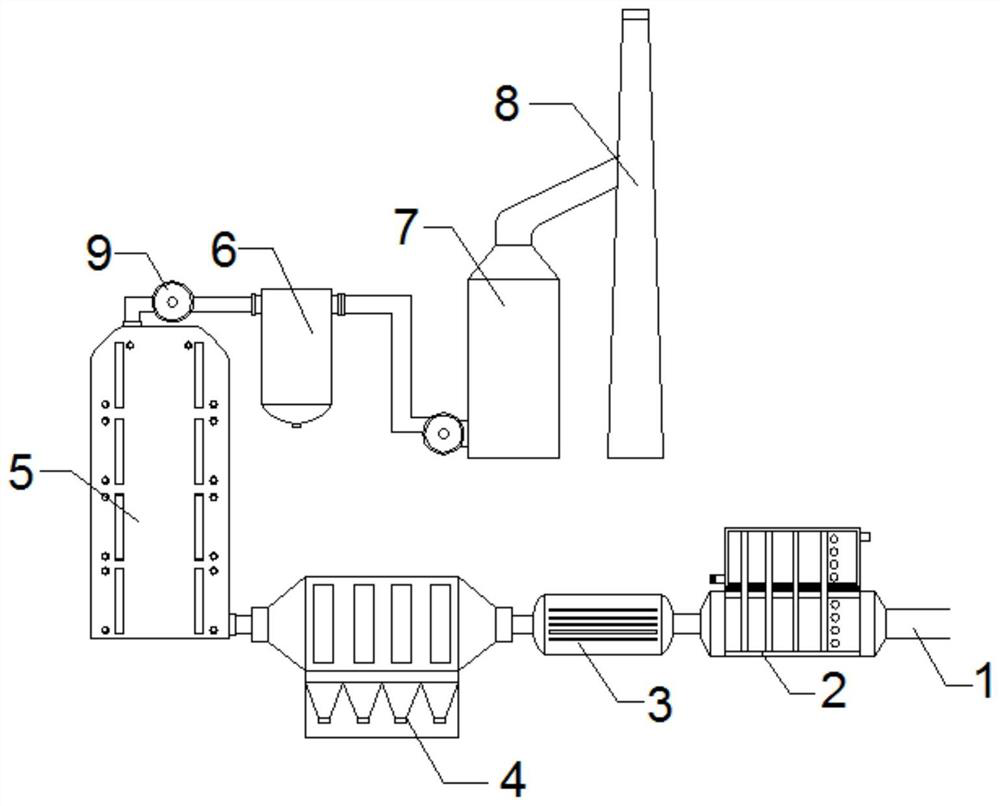
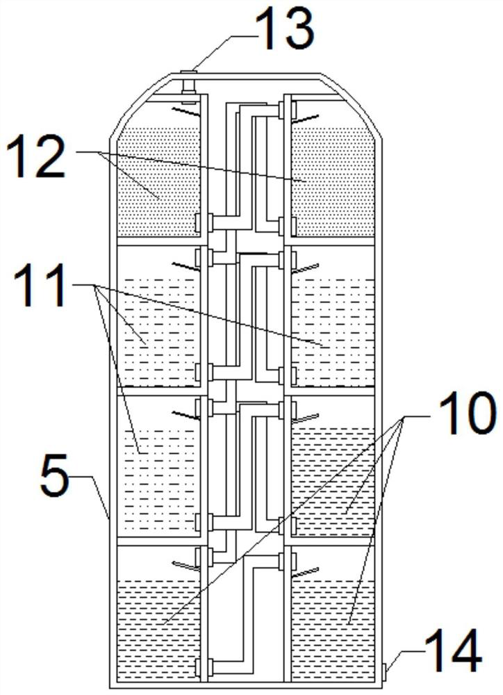
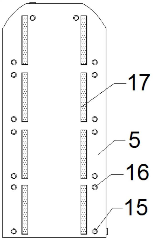
[0024] Such as Figure 1-3 As shown, a waste gas recovery system for reducing condensate includes a smoke pipe 1, a flue gas treatment tank 5 and a primary treatment chamber 10, and the smoke exhaust end of the smoke pipe 1 is connected to a waste heat recovery device 2 through a flange. The smoke outlet end of the waste heat recovery device 2 is connected with a water-cooled flue 3, and the outlet end of the water-cooled flue 3 is connected with a bag filter 4, and a flue gas treatment tank 5 is arranged on one side of the bag filter 4, and the flue gas The bottom of one side of the gas treatment tank 5 is provided with an air inlet nozzle 14, and the top of the flue gas treatment tank 5 is provided with an air outlet nozzle 13. The gas outlet 13 connected to the flue gas treatment tank 5 is connected with a spiral steam-water separator 6 through a gas pipe, and the gas outlet of the spiral steam-water separator 6 is connected with a desulfurization tower 7 through a pipeline...

Embodiment 2

[0038] Such as Figure 1-3As shown, a waste gas recovery system for reducing condensate includes a smoke pipe 1, a flue gas treatment tank 5 and a primary treatment chamber 10, and the smoke exhaust end of the smoke pipe 1 is connected to a waste heat recovery device 2 through a flange. The smoke outlet end of the waste heat recovery device 2 is connected with a water-cooled flue 3, and the outlet end of the water-cooled flue 3 is connected with a bag filter 4, and a flue gas treatment tank 5 is arranged on one side of the bag filter 4, and the flue gas The bottom of one side of the gas treatment tank 5 is provided with an air inlet nozzle 14, and the top of the flue gas treatment tank 5 is provided with an air outlet nozzle 13. The gas outlet 13 connected to the flue gas treatment tank 5 is connected with a spiral steam-water separator 6 through a gas pipe, and the gas outlet of the spiral steam-water separator 6 is connected with a desulfurization tower 7 through a pipeline,...


PUM


Abstract

The invention discloses an exhaust gas recovery system capable of reducing condensate. The system comprises a smoke pipe, a smoke treatment tank and a primary treatment chamber, a smoke exhaust end ofthe smoke pipe is connected with a waste heat recoverer through a flange, a smoke outlet end of the waste heat recoverer is connected with a water cooling flue, a gas outlet end of the water coolingflue is connected with a bag-type dust collector, a smoke treatment tank is arranged on one side of the bag-type dust collector, a gas inlet nozzle is formed in the bottom of one side of the smoke treatment tank, and a gas outlet nozzle is formed in the top of the smoke treatment tank. According to the waste gas recovery system, multi-stage waste removal treatment is utilized, dust removal and dehydration treatment is carried out on waste gas, condensate and water vapor are reduced, and multi-stage cooling and dust falling treatment is carried out through the carbon dioxide absorbent liquid, the desulfurizing agent liquid and the denitrifying agent liquid while carbon dioxide, sulfur and nitrate are removed, so that the environment-friendly coefficient of the waste gas treated by the wastegas recovery system is higher when the waste gas is discharged.

Description

technical field [0001] The invention belongs to the technical field of waste gas treatment, and in particular relates to a waste gas recovery system for reducing condensate. Background technique [0002] The current waste gas recovery system used for flue gas emission is relatively simple. When dealing with flue gas with different components, it needs personnel to reassemble the corresponding purification equipment, which is inconvenient to use, and there is no component that can directly replace the treatment agent. Contents of the invention [0003] The object of the present invention is to provide an exhaust gas recovery system that reduces condensate, so as to solve the problems raised in the background art above. [0004] In order to achieve the above object, the present invention provides the following technical solution: a waste gas recovery system for reducing condensate, including a smoke pipe, a flue gas treatment tank and a primary treatment chamber, the smoke e...

Claims


Application Information

Patent Timeline
Patent Type & Authority Applications(China)
IPC IPC(8): B01D53/48B01D53/56B01D53/62B01D53/75B01D53/78
CPCB01D53/48B01D53/56B01D53/62B01D53/75B01D53/78B01D2257/504B01D2258/0283Y02A50/20
Inventor 陈义梁罗俊苏杰
Owner 潮州市中乾环境科技有限公司
Why Eureka
Try Eureka