Guide blade shaft sleeve assembling and disassembling tool

A guide vane shaft sleeve and tool technology, applied in the manufacture of tools, hand-held tools, etc., can solve the problems of aggravation of out-of-synchronization, personal injury, insufficient rigidity and easy deformation, etc., and achieve reasonable cost and construction period, control cost and construction period , The effect of improving the process precision

Inactive Publication Date: 2020-09-18
STATE GRID CORP OF CHINA +1
View PDF12 Cites 2 Cited by
  • Summary
  • Abstract
  • Description
  • Claims
  • Application Information

AI Technical Summary

Problems solved by technology

[0006] (1) Difficulty in disassembly: the parts to be disassembled can be selected with limited stress points, and are affected by factors such as precision, material, and dirt and hardening generated during operation. It is difficult to disassemble and assemble using existing technologies, and Difficult to balance safety and quality
[0007] (2) The disassembly tool is heavy: in the prior art, the beam structure is used for disassembly, and the strength of the beam is the key, and the rigidity is insufficient and easy to deform, but when the rigidity is sufficient, the weight will increase significantly
And other auxiliary devices are mostly made temporarily, heavy, laborious to operate and difficult to keep
[0008] (3) Uneven force: At least two jacks are lifted synchronously. Even if the "one drag N" hydraulic device is used, that is, the use of a splitter to achieve jack synchronization, it is difficult to ensure height synchronization. Ordinary screw and rack jacks are even more far from
Moreover, the structure of the beam itself has defects, which are prone to deformation, offset, etc., which will also aggravate the degree of asynchrony
[0009] (4) Parts are vulnerable: the guide vane shaft sleeve is mostly made of cast iron, cast copper, polymer materials, composite materials, self-lubricating materials, etc. Improper operation of existing disassembly tools can easily cause damage
[0010] (5) Rough workmanship: The workmanship, precision and material of the shaft sleeve determine that whether it is dismantled or installed, it should be operated strictly in accordance with the workmanship and technical requirements. Destructive demolition, etc., should be strictly prohibited
However, the existing removal tools will reduce the installation accuracy and even cause safety hazards
[0011] (6) High risk: uneven force, device deformation, rough workmanship, etc., which can easily cause personal injury and component damage, etc.
Especially in the case of beam deformation, deflection, unsynchronized jacks, improper operation, etc., the degree of danger increases sharply

Method used


Image

  • Guide blade shaft sleeve assembling and disassembling tool
  • Guide blade shaft sleeve assembling and disassembling tool
  • Guide blade shaft sleeve assembling and disassembling tool

Examples


Embodiment Construction

[0031] It should be noted that, in the case of no conflict, the embodiments in the present application and the features in the embodiments can be combined with each other. The present invention will be described in detail below with reference to the accompanying drawings and examples.

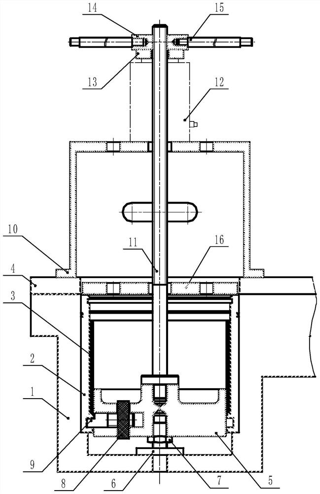
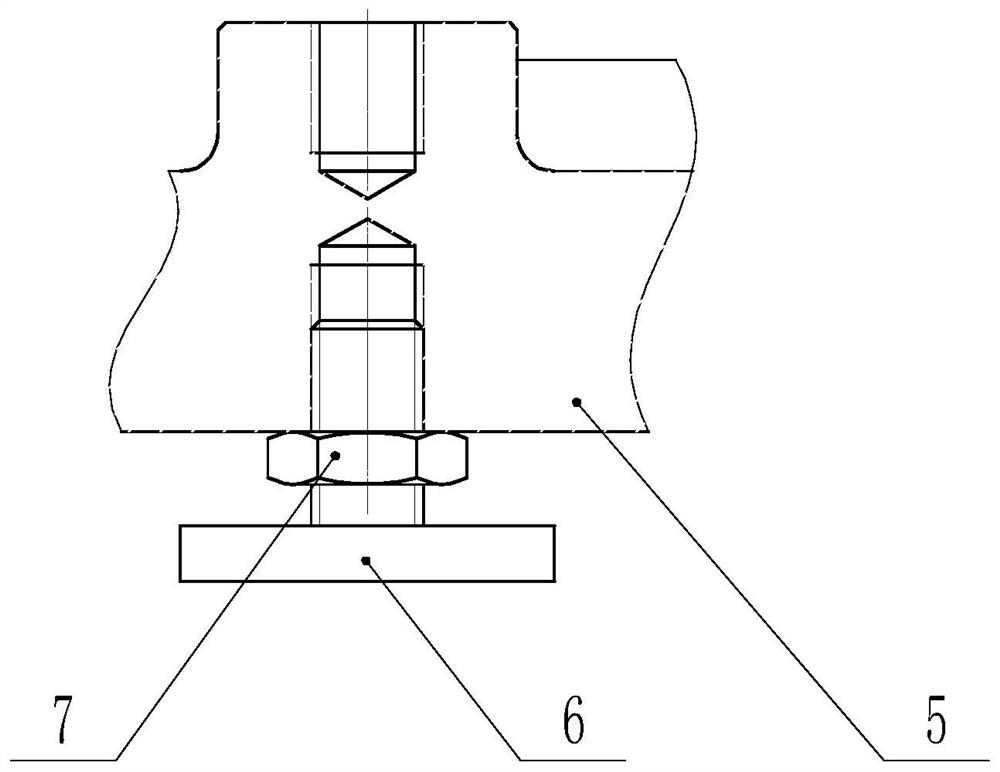
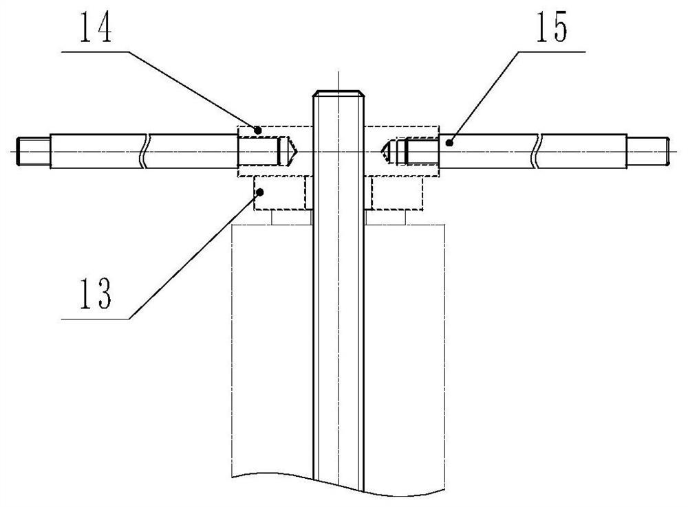
[0032] Such as Figure 1 to Figure 5 As shown, the embodiment of the present invention provides a tool for removing and installing a guide vane shaft sleeve, which includes a sleeve 10 , a hollow jack 12 , a lead screw 11 and a chuck 5 . The lower end of the sleeve 10 is open and the upper end is closed. The lower end of the sleeve 10 abuts against the wear-resistant plate 4 on the upper end of the bottom ring 1 . The sleeve 10 has an accommodation space for accommodating the shaft sleeve 2 to be disassembled. The hollow jack 12 is arranged coaxially with the sleeve 10 , and the lower end of the hollow jack 12 abuts against the top wall of the sleeve 10 . The lead screw 11 is coaxially instal...


PUM


Abstract

The invention provides a guide blade shaft sleeve assembling and disassembling tool. The guide blade shaft sleeve assembling and disassembling tool comprises a sleeve, a hollow jack, a lead screw anda chuck. The lower end of the sleeve is opened, the upper end of the sleeve is closed, the lower end of the sleeve abuts against a wear-resistant plate at the upper end of a bottom ring in a connection mode, and the sleeve comprises a holding space which is used for holding a shaft sleeve to be disassembled. The hollow jack and the sleeve are coaxially arranged, and the lower end of the hollow jack abuts against the top wall of the sleeve in a connection mode. The lead screw coaxially penetrates through the sleeve and the hollow jack, and the upper end of the lead screw is arranged above the hollow jack. A rotary twisting assembly which is used for driving the lead screw to move in the vertical direction is arranged at the upper end of the lead screw and abuts against the upper end of thehollow jack in a connection mode. The lower end of the lead screw is arranged below the hollow jack. The upper end of the chuck is connected with the lower end of the lead screw, and a clamping jaw assembly which can stretch out and draw back in the radial direction of the chuck is arranged on the periphery of the chuck and can be connected with an annular groove in the inner wall of the shaft sleeve in a clamped mode. The guide blade shaft sleeve assembling and disassembling tool is high in safety, accurate in technology and convenient and fast to operate, and the degree of the damage to theshaft sleeve is substantially reduced.

Description

technical field [0001] The invention relates to the field of assembly and disassembly tools, in particular to a assembly and disassembly tool for guide vane shaft sleeves. Background technique [0002] The water guide mechanism is one of the important components of the hydro-generator set. Its main functions are: first, to adjust the water flow of the turbine according to the load change, thereby adjusting the output of the unit; The scientific allocation of resources, efficient and stable impact on the runner, realizes the smooth conversion of water energy to mechanical energy. The abnormality of the water guide mechanism often causes a series of problems such as submergence, vibration, tripping, and load shedding of the unit. How to ensure the safe and stable operation of the water guiding mechanism has always been an important content in the design, manufacture, installation, commissioning, operation and maintenance of hydroelectric generating units. [0003] The water ...

Claims


Application Information

Patent Timeline
Patent Type & Authority Applications(China)
IPC IPC(8): B25B27/02
CPCB25B27/023B25B27/026
Inventor 马金才康百东巩颖攀王彦辉温铁军白永皓尹德亮李来生王泽宇姜海山王长辉刘春涛顾文海李悦乔丛
Owner STATE GRID CORP OF CHINA
Why Eureka
Try Eureka