Drilling equipment used before assembling of storage cabinet

A technology for drilling equipment and storage cabinets, which is used in fixed drilling machines, multi-purpose machinery, wood processing appliances, etc. Deeply unified, easy-to-use effects

Active Publication Date: 2020-09-18
TRANTEX PROD CO LTD
View PDF23 Cites 19 Cited by
  • Summary
  • Abstract
  • Description
  • Claims
  • Application Information

AI Technical Summary

Problems solved by technology

[0005] In order to overcome the shortcomings of manual drilling of locker boards resulting in different sizes of holes, and manual handling of the drilled locker boards requires a lot of effort, resulting in low drilling efficiency. The technical problems to be solved are: A pre-assembly drilling device for lockers that can automatically and intermittently replace the wooden boards of the locker that need to be drilled, can automatically drill the wooden boards of the locker, and can also automatically store the drilled wooden boards

Method used


Image

  • Drilling equipment used before assembling of storage cabinet
  • Drilling equipment used before assembling of storage cabinet
  • Drilling equipment used before assembling of storage cabinet

Examples


Embodiment 1

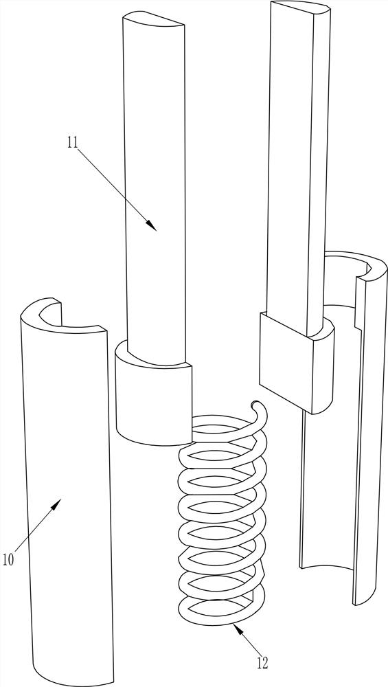
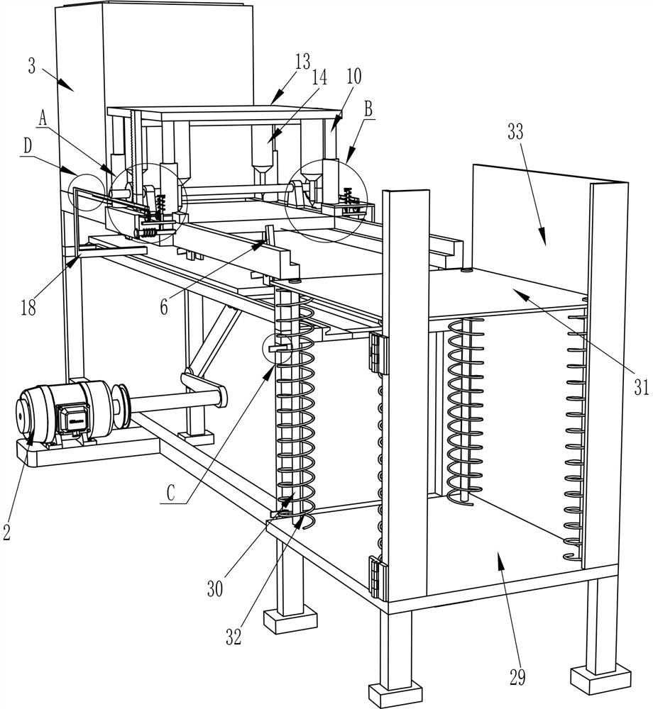
[0026] A device for drilling holes prior to assembly of lockers such as Figure 1-4 As shown, it includes a frame 1, a motor 2, a blanking box 3, a slide plate 5, an L-shaped push rod 6, a first connecting rod 7, a second connecting rod 8, a transmission mechanism 9, a sliding sleeve 10, a sliding rod 11, First spring 12, placement plate 13, electric drill 14, first rack 15, first rotating shaft 16 and sector gear 17, the front side lower part of frame 1 is fixed with motor 2 by bolt, the top left side of frame 1 A blanking box 3 is installed between them, and the upper part of the frame 1 is slidably connected to the slide plate 5, the slide plate 5 is located below the blanking box 3, and the top of the slide plate 5 is evenly spaced and rotated to be equipped with an L-shaped push rod 6, and an L-shaped push rod 6 The quantity is three, the gravity of the left part of the L-shaped push rod 6 is greater than the gravity of the right part, the output shaft of the motor 2 is f...

Embodiment 2

[0029] On the basis of Example 1, such as figure 2 , Figure 4 , Figure 5 and Figure 7 Shown, also comprise L-shaped rack 18, support frame 19, second rotating shaft 20, first gear 21, second gear 22, second rack 23, telescoping link 24, second spring 25, stop bar 26 and The third spring 28, the top front and rear sides of the slide plate 5 are all connected with L-shaped racks 18, the front and rear sides of the top of the frame 1 are symmetrically equipped with a support frame 19, the support frame 19 is located on the right side of the placement plate 13, and the support frame 19 top Opening is arranged, and the second rotating shaft 20 is equipped with the second rotating shaft 20 in the supporting frame 19 of front and rear sides, and the outside of the second rotating shaft 20 is equipped with a first gear 21, and the top of the first gear 21 passes through the opening that supporting frame 19 offers, L The gear rack 18 meshes with the first gear 21, the second gea...

Embodiment 3

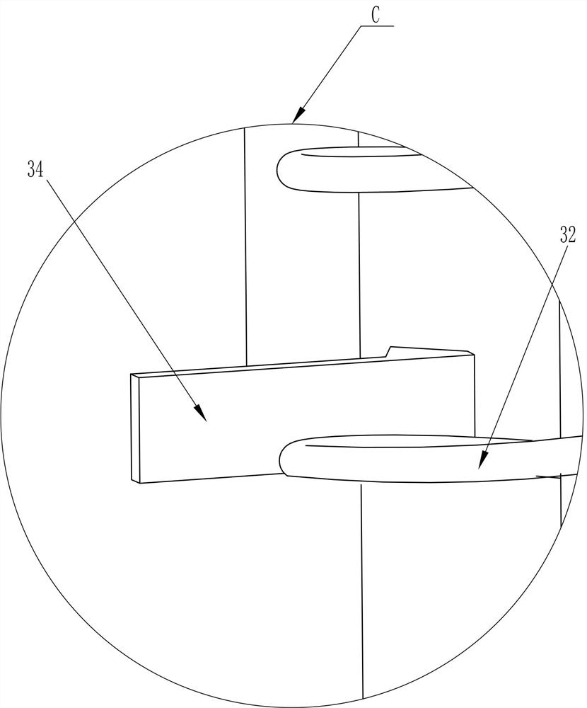
[0032] On the basis of Example 2, such as figure 1 , figure 2 and Figure 6 As shown, it also includes a first support plate 29, a support rod 30, a second support plate 31, a fourth spring 32, a baffle plate 33 and an L-shaped rubber clamp 34, and the right side of the frame 1 is equipped with a first support plate 29. The top, front, rear, left, and right sides of the top of the first support plate 29 are connected with support rods 30, and the support rod 30 is slidably connected with a second support plate 31, and a fourth support plate 31 is connected between the first support plate 29 and the second support plate 31. The spring 32 and the fourth spring 32 are all wound on the support rod 30, the front and rear sides of the first support plate 29 top are connected with baffle plates 33, the front baffle plate 33 is a reverse setting, and the front side baffle plate 33 left An L-shaped rubber clamp 34 is installed on the rear side of the part, and the L-shaped rubber cl...


PUM


Abstract

The invention relates to drilling equipment, in particular to drilling equipment used before assembling of a storage cabinet. The technical problem to be solved is to how to provide the drilling equipment used before assembling of the storage cabinet, in which a storage cabinet wood board needing to be drilled can be automatically and intermittently replaced, the storage cabinet wood board can beautomatically drilled, and the drilled wood board can be automatically stored. The drilling equipment used before assembling of the storage cabinet comprises a rack, a motor, a discharging box, a sliding plate and the like; and the motor is installed in the middle of the lower portion of the rack through bolts, the discharging box used for storing plates is installed between the tops of the rack,and the sliding plate is arranged on the upper portion of the rack in a sliding mode and located below the discharging box. Through the motor, the sliding plate, an L-shaped push rod, a first connecting rod and the like, a plate needing to be drilled can be automatically replaced, the plate can be transported, and the fixed position of the plate can be drilled through a transmission mechanism, a sector gear, a first rotating shaft, a placing plate, an electric drill and the like.

Description

technical field [0001] The invention relates to a drilling device, in particular to a drilling device before assembly of a locker. Background technique [0002] Lockers are generally assembled from plates. Before assembling the lockers, it is necessary to drill holes in the wooden boards, install bolts and other complicated processes to complete the assembly of the lockers, so that the lockers can be used more stable. [0003] Existing drilling device, as the Chinese patent of patent notification number CN208714157U discloses a kind of full-automatic drilling device, comprises bench, drilling support, control cabinet, and drilling support is arranged on the bench, is characterized in that: A slide rail is set on the stand, and a body fixing table is set on the slide rail. The body fixing table is driven by a screw motor and a screw rod arranged on the stand, and is in a state of feeding in a direction perpendicular to the drilling support on the slide rail. The upper and l...

Claims


Application Information

Patent Timeline
Patent Type & Authority Applications(China)
IPC IPC(8): B27C3/04B27C9/04
CPCB27C3/04B27C9/04
Inventor 黄杰
Owner TRANTEX PROD CO LTD
Why Eureka
Try Eureka