
Pulverized coal circulation pyrolysis reactor

A technology of pyrolysis reactor and pyrolysis reaction, which is applied in special forms of dry distillation, petroleum industry, coking oven, etc., and can solve the problems of secondary cracking of pyrolysis oil and gas, short residence time of pulverized coal, and low yield of pyrolysis products, etc. , to achieve the effect of reducing the residence time, weakening the secondary cracking reaction and rapid separation

Pending Publication Date: 2020-09-18
HUADIAN ELECTRIC POWER SCI INST CO LTD
View PDF3 Cites 1 Cited by
  • Summary
  • Abstract
  • Description
  • Claims
  • Application Information

AI Technical Summary

Problems solved by technology

[0006] The purpose of the present invention is to overcome the above-mentioned deficiencies in the prior art, and provide a pulverized coal circulation pyrolysis reactor with a reasonable structural design to solve the problem of uneven heat transfer due to the mixing of heat carrier gas and large particle pulverized coal at different temperatures , the residence time of pulverized coal in the reactor is short, the pyrolysis is insufficient, the yield of pyrolysis products is low, and the secondary cracking of pyrolysis oil and gas is serious.

Method used


Image

  • Pulverized coal circulation pyrolysis reactor
  • Pulverized coal circulation pyrolysis reactor
  • Pulverized coal circulation pyrolysis reactor

Examples


Embodiment Construction

[0027] The present invention will be further described in detail below in conjunction with the accompanying drawings and examples. The following examples are explanations of the present invention and the present invention is not limited to the following examples.

[0028] Example.

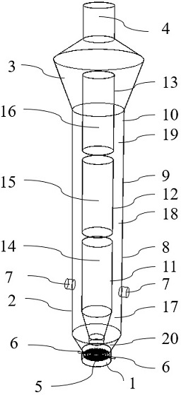
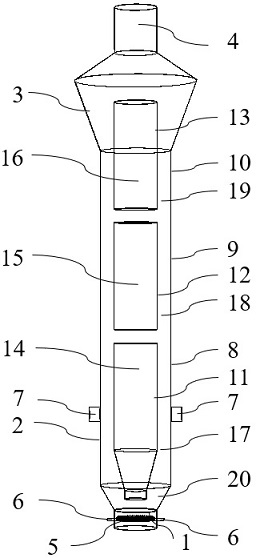
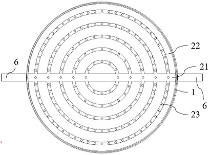
[0029] see Figure 1 to Figure 3 , in this embodiment, a pulverized coal circulating pyrolysis reactor, including a pyrolysis product delivery section 4, a reactant and product separation section 3, a circulating pyrolysis reaction section 2 and a heat carrier gas inlet arranged in sequence from top to bottom segment 1.

[0030]The pyrolysis product delivery section 4 is used to quickly lead the pyrolysis oil and gas products out of the pulverized coal pyrolysis reactor, and weaken the secondary cracking reaction of the pyrolysis oil and gas.

[0031] The reactant and product separation section 3 is used to reduce the superficial gas velocity, efficiently and quickly separate the pyrolysis produc...


PUM


Abstract

The invention discloses a pulverized coal circulation pyrolysis reactor, which comprises a pyrolysis product conveying section, a reactant and product separation section, a circulation pyrolysis reaction section and a hot carrier gas inlet section, which are sequentially arranged from top to bottom. The pyrolysis product conveying section is used for quickly leading a pyrolysis oil gas product outof the pulverized coal pyrolysis reactor; the reactant and product separation section is used for reducing the apparent gas velocity and efficiently and quickly separating a pyrolysis product from incompletely reacted pulverized coal; the circulation pyrolysis reaction section comprises a first-section pyrolysis reaction area, a second-section pyrolysis reaction area, a third-section pyrolysis reaction area, a pulverized coal feeding port and a material returning section, and is used for overall ordered circulation of pulverized coal and hot carrier gas, namely, the hot carrier gas and large-particle pulverized coal directionally flow in the circulation pyrolysis reaction section, and multiple times of circulation are formed. The flowing environment of the pulverized coal and the hot carrier gas is effectively improved, the mixing and heat exchange behaviors of the pulverized coal and the hot carrier gas are ensured, the sufficient pyrolysis of the pulverized coal is realized, the pyrolysis oil gas secondary cracking reaction is weakened, and the pyrolysis oil gas yield is improved.

Description

technical field [0001] The invention relates to the technical fields of coal chemical industry and energy, in particular to a pulverized coal circulation pyrolysis reactor. Background technique [0002] my country is the world's largest coal producer and consumer. The energy characteristics of "rich coal, poor oil, and little gas" determine that for a long period of time, coal's position as the leading energy consumption in my country will not be shaken. my country is rich in low-rank coal resources, accounting for about 42.46% of the country's proven coal resources. The chemical structure of low-rank coal has more side chains, higher hydrogen and oxygen content, and has the characteristics of high moisture content, low calorific value, good chemical reactivity, flammability and fragility, and is not suitable for long-distance transportation and storage. Existing low-rank coal processing and utilization technologies include direct combustion for power generation, direct liq...

Claims


Application Information

Patent Timeline
IPC IPC(8): C10B53/04
CPCC10B53/04
Inventor 彭丽石战胜董方马治安敬旭业徐波
Owner HUADIAN ELECTRIC POWER SCI INST CO LTD
Learn More