Rapid humidifying and semi-digesting method for fly ash

A fast and stirring tank technology, which is applied in the direction of instruments, measuring devices, scientific instruments, etc., can solve the problems of severe crushing, the steelmaking dust removal ash spherical body cannot bear the impact force, and the converter smelting can no longer be used to improve the service life. Facilitates linear motion and prevents wear and damage

Active Publication Date: 2020-09-18
CHONGQING ZHONGZHA METALLURGY RENEWABLE RESOURCESCO
View PDF6 Cites 1 Cited by
  • Summary
  • Abstract
  • Description
  • Claims
  • Application Information

AI Technical Summary

Problems solved by technology

[0004] The invention provides a quick humidification and semi-digestion method for dedusting ash to solve the problem that the steelmaking dedusting ash sp...

Method used


Image

  • Rapid humidifying and semi-digesting method for fly ash
  • Rapid humidifying and semi-digesting method for fly ash
  • Rapid humidifying and semi-digesting method for fly ash

Examples


Embodiment 1

[0036] Embodiment 1 is basically as attached figure 1 with figure 2 Shown:

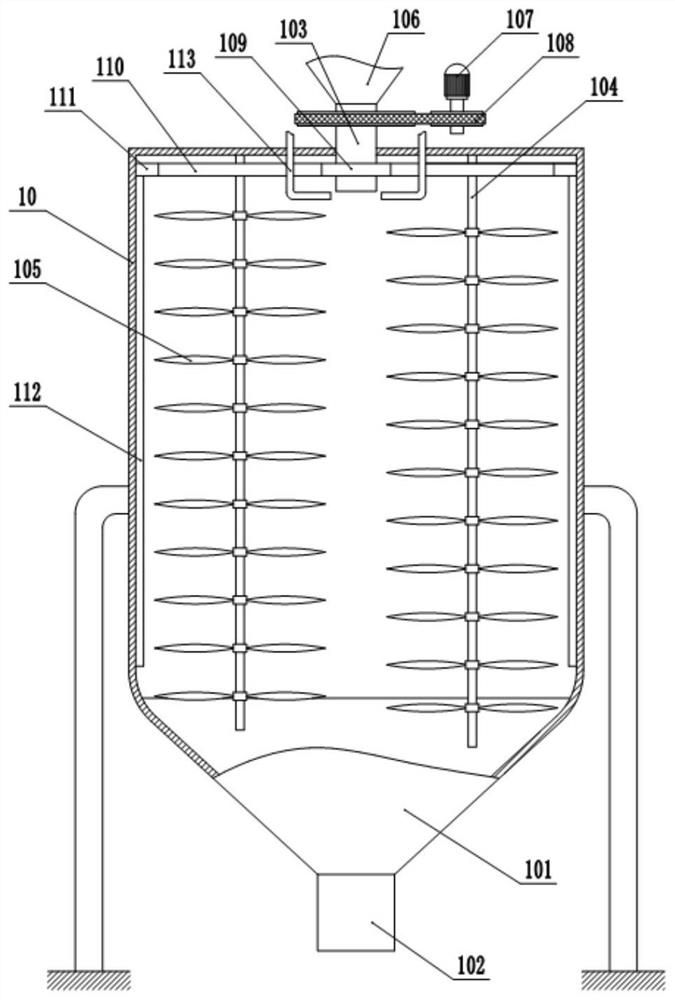
[0037] A quick humidification and semi-digestion method for dedusting dust. In this method, a stirring tank is used to complete the humidification and semi-digestion treatment of steelmaking dedusting ash, and at the same time, it is mixed with iron oxide scale or magnetic separation powder. The stirring tank includes a support frame and a tank body 10, the tank body 10 is fixed on the support frame, the top of the tank body 10 is in a closed state, an inverted tapered section 101 is welded at the bottom of the tank body 10, and a discharge pipe 102 is welded at the bottom of the inverted tapered section 101, and the inside of the discharge pipe 102 An opening and closing valve is provided, and a stirring mechanism is provided in the tank body 10 .

[0038] In this embodiment, the stirring mechanism includes a hollow shaft 103 and a plurality of stirring rods 104 that are rotatably connected to the...

Embodiment 2

[0046] Embodiment 2 is basically as attached figure 2 with image 3 Shown:

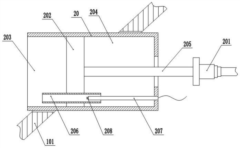
[0047] The difference from Embodiment 1 is that a humidity detection unit is provided on the side wall of the inverted tapered section 101. In this embodiment, the opening and closing valve is a solenoid valve, wherein the solenoid valve is controlled to open and close by the humidity detection unit. In the tank body 10 A mounting hole is provided on the inverted tapered section 101, and the humidity detection unit is fixed in the mounting hole. The humidity detection unit specifically includes a cylinder body 20 and a driver 201, wherein a slider 202 is slidably connected to the cylinder body 20, and the slider 202 will The cylinder body 20 is divided into a sampling chamber 203 and a detection chamber 204. A connecting rod 205 located in the detection chamber 204 is fixed on the slider 202, wherein the driving member 201 drives the connecting rod 205 to perform linear reciprocating motion. In this...

Embodiment 3

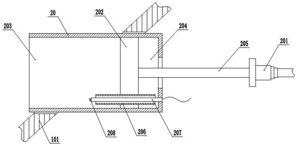
[0051] Embodiment 3 is basically as attached Figure 4 Shown:

[0052] The difference from Embodiment 2 is that the detection chamber 204 is a closed chamber, the connecting rod 205 is in sliding and sealing connection with the cylinder body 20, and the side wall of the detection chamber 204 is provided with an inlet check valve 209 and an outlet check valve 210, When the volume in the detection chamber 204 increases and the air pressure decreases, the air intake check valve 209 opens, and the outside air is filled into the detection chamber 204. When the volume in the detection chamber 204 decreases and the air pressure increases, the air outlet is one-way. The valve 210 is opened, the gas in the detection chamber 204 is discharged, and a constant temperature heating element is electrically connected to the detection chamber 204. The heating temperature of the constant temperature heating element is 32-35°C. The strip-shaped groove 211 is arranged along the axial direction o...


PUM


Abstract

The invention relates to the technical field of resource recovery, and particularly discloses a rapid humidifying and semi-digesting method for fly ash. The method includes the following steps that 1,sampling is conducted, the mass ratio of calcium oxide in the steelmaking fly ash is determined, and the water amount X required by the complete reaction of calcium oxide to calcium hydroxide; 2, thesteelmaking fly ash is added into a stirring tank, water is sprayed into the stirring tank, the steelmaking fly ash entering the stirring tank makes contact with the water, then is mixed by a stirring mechanism in the stirring tank for semi-digestion, and finally is discharged from a discharging pipe at the bottom of the stirring tank, and the total mass of the added water is 20%-60% of X in thestep 1. According to the technical scheme, the steelmaking fly ash can be rapidly humidified and semi-digested, then iron oxide scale or magnetic separation powder and a binding agent are added and mixed together for a chemical reaction, and later reaction and ball pressing procedures are facilitated.

Description

technical field [0001] The invention relates to the technical field of resource recovery, in particular to a method for rapid humidification and semi-digestion of dedusting ash. Background technique [0002] In the field of steelmaking, dust removal (or steelmaking dust removal) can be roughly divided into two categories according to the needs and properties of dust removal settings: flue gas dust removal and environmental dust removal. Flue gas dust removal is the smoke exhaust process of steelmaking production The iron-containing dust generated in the environment, while the environmental dust removal dust is the dust generated in the environment of the production plant. [0003] Since the dust ash produced in the steelmaking process also contains a large amount of metal components, it is necessary to recycle the dust ash. In addition, because the dust ash from steelmaking contains high alkali metal elements, it cannot be directly used for sintering or blast furnaces. Retu...

Claims


Application Information

Patent Timeline
IPC IPC(8): C22B1/00G01N33/00
CPCC22B1/005G01N33/00Y02P10/20
Inventor 吴晓伟
Owner CHONGQING ZHONGZHA METALLURGY RENEWABLE RESOURCESCO
Why Eureka
Try Eureka