
High-power laser coupling structure

A coupling structure, high-power technology, applied in the coupling of optical waveguides, light guides, optics, etc., can solve the problems of large transmission loss, difficult parts processing and assembly, abnormal absorption of laser energy at the fiber end face, etc., to reduce the laser energy density. , The effect of low loss and high reliability transmission, reducing the difficulty of assembly process

Inactive Publication Date: 2020-09-18
CHINA AEROSPACE TIMES ELECTRONICS CORP
View PDF3 Cites 4 Cited by
  • Summary
  • Abstract
  • Description
  • Claims
  • Application Information

AI Technical Summary

Problems solved by technology

[0003] 1. When the traditional single-mode optical fiber connector is used for high-power laser transmission, due to the high laser power density of the output and input end faces of the optical fiber, once the damage threshold of the optical fiber material is exceeded, it is easy to cause the end face of the optical fiber to burn and cannot continue to transmit light energy
[0004] 2. When the high-power laser passes through the output and input end faces of the optical fiber, tiny surface quality defects on the end face of the optical fiber, such as impurities, scratches and micro-defects, etc., will cause abnormal absorption of laser energy and cause the end face of the optical fiber to be burned, making it impossible to continue to transmit light energy
[0005] 3. When the high-power laser passes through the output and input end faces of the optical fiber, any pollutants on the end face of the optical fiber, such as dust, stains, etc., will cause abnormal absorption of laser energy, and cause the end face of the optical fiber to be burned, making it impossible to continue to transmit light energy
[0006] 4. In the process of repeated plugging and unplugging of traditional physical contact single-mode fiber optic connectors, the end face of the fiber is susceptible to wear. Once the end face of the fiber is damaged, when transmitting high-power lasers, the damaged end face of the fiber is prone to abnormal laser energy. Absorption, and cause the end face of the fiber to burn, unable to continue to transmit light energy
[0007] For the above application requirements of high-power laser single-mode transmission, there are currently non-contact optical fiber connectors that use lens beam expansion. However, this type of connector uses lenses for non-contact connection between optical fibers. The disadvantage is that the transmission loss is large and the interchangeability is poor. , parts processing and assembly are difficult and costly

Method used


Image

  • High-power laser coupling structure
  • High-power laser coupling structure
  • High-power laser coupling structure

Examples


Embodiment

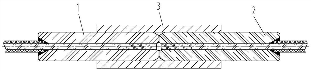
[0034] Such as figure 1 Shown is a schematic diagram of the structure of the coupling device. It can be seen from the figure that a high-power laser coupling structure includes a first pin 1 , a second pin 2 and a sleeve 3 . The outer diameter of the ferrule 202 has extremely high accuracy, and the tolerance is less than 0.5 μm. The first pin 1 and the second pin 2 are radially fixed by the sleeve 3, and the first pin 1 and the sleeve 3, and the second High-precision interference fit is adopted between the two pins 2 and the bushing 3 to ensure that the axes between the two are precisely centered.

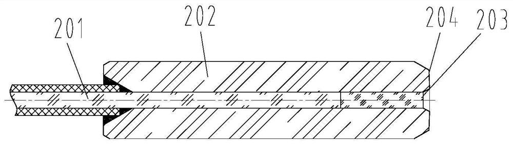
[0035] Such as figure 2 Shown is a schematic diagram of the structure of the fiber group. It can be seen from the figure that the first ferrule 1 and the first ferrule 2 both include a fiber group 201 , a ferrule 202 , a front face 203 of the fiber group and a front face 204 of the ferrule. Among them, the ferrule 202 is a hollow structure along the axial direction, and the conc...


PUM


Abstract

A high-power laser coupling structure comprises a first contact pin, a second contact pin and a sleeve. The optical fiber group is permanently fixed in the insertion core by using epoxy glue; the contact piece is placed in the shell; and the contact pieces are in butt joint in the sleeve. The invention is suitable for high-power laser transmission, has the advantages of low insertion loss and lowlaser energy density of the optical end face, effectively prevents the optical end face from being ablated by laser, and has low processing difficulty.

Description

technical field [0001] The invention relates to the field of optical fiber connectors, in particular to a high-power optical fiber connector. Background technique [0002] Traditional single-mode optical fiber connectors mostly use physical connection methods, that is, the end faces of single-mode optical fibers are in direct contact to achieve low-loss transmission of optical signals. This connection method is not suitable for high-power laser transmission applications, mainly in the following aspects: [0003] 1. When the traditional single-mode optical fiber connector is used for high-power laser transmission, due to the high laser power density of the output and input end faces of the optical fiber, once the damage threshold of the optical fiber material is exceeded, it is easy to cause the end face of the optical fiber to burn and cannot continue to transmit light energy. [0004] 2. When the high-power laser passes through the output and input end faces of the optical...

Claims


Application Information

Patent Timeline
IPC IPC(8): G02B6/26G02B6/38
CPCG02B6/262G02B6/3807
Inventor 黄媛媛白江浩徐金玲李鑫姚梦远张嘉骏李翔甘军宁黄鸿宇
Owner CHINA AEROSPACE TIMES ELECTRONICS CORP
Features
  • Generate Ideas
  • Intellectual Property
  • Life Sciences
  • Materials
  • Tech Scout
  • Unparalleled Data Quality
  • Higher Quality Content
  • 60% Fewer Hallucinations
Learn More