Sterilization line cleaning method and sterilization line

A technology for processing lines and cleaning liquids, applied in chemical instruments and methods, liquid processing, cleaning methods and utensils, etc., can solve the problems of expensive equipment investment, increased number of valves, complex valve structure, etc. The valve structure is simplified, the effect of lightening the amount

Active Publication Date: 2020-09-18
DAI NIPPON PRINTING CO LTD
View PDF11 Cites 0 Cited by
  • Summary
  • Abstract
  • Description
  • Claims
  • Application Information

AI Technical Summary

Problems solved by technology

However, changing the flow path of the product liquid, cleaning liquid in CIP, or heating fluid for SIP by valve operation in parallel flow paths complicates the valve structure and increases the number of valves, thereby reducing equipment investment. the amount becomes expensive
In addition, cleaning fluid, etc. may be mixed into the product liquid due to valve operation error, residual liquid, and damage or leakage of the valve.

Method used


Image

  • Sterilization line cleaning method and sterilization line
  • Sterilization line cleaning method and sterilization line
  • Sterilization line cleaning method and sterilization line

Examples


Embodiment approach 1

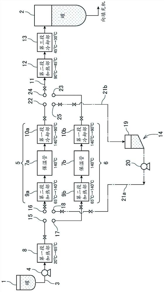
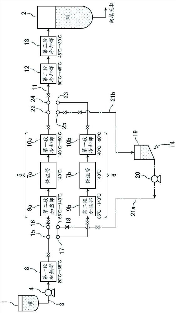
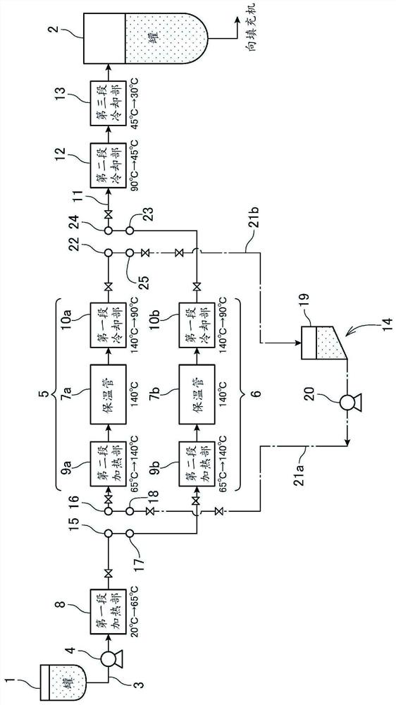
[0042] Installed in the piping system of the aseptic filling machine that handles large-capacity beverages and other product liquids figure 1 Sterilization treatment line as shown.

[0043] exist figure 1 In the figure, reference numeral 1 indicates an upstream side tank for storing a product liquid such as a prepared unsterilized beverage, and reference number 2 indicates a downstream side tank for temporarily storing the sterilized product liquid before supplying it to a filling machine not shown in the figure. .

[0044] The upstream side tank 1 and the downstream side tank 2 can each store a large-capacity product liquid, for example, each has a volume capable of storing several tons to a dozen tons of the product liquid. In addition, the upstream tank 1 keeps the product liquid before sterilization at normal temperature, for example, about 20°C, and the downstream tank 2 keeps the product liquid after sterilization at normal temperature, for example, about 30°C.

[004...

Embodiment approach 2

[0070] In Embodiment 2, instead of performing only CIP in the intermediate piping system as in Embodiment 1 for the intermediate piping system on standby, SIP is performed after CIP, and positive pressure processing is further performed. By performing SIP in the intermediate piping system, positive pressure processing is performed and the standby is performed. Therefore, after the flow path is switched, SIP is not performed on the intermediate piping system, the downstream side pipe 11, and the downstream side tank 2, and the previous product liquid After removal, a new product liquid can be supplied immediately, and compared with the case of Embodiment 1, switching time can be shortened significantly, and productivity can be improved.

[0071] Such as Figure 5 As shown, in addition to the sterilization treatment line of Embodiment 1, the sterilization treatment line of Embodiment 2 is provided with a SIP device 27 that performs SIP to sterilize the interior of the intermedia...


PUM


Abstract

The invention provides a sterilization line cleaning method. A sterilization line comprising an upstream-side tank (1) and a downstream-side tank (2) for respectively storing a product liquid which are connected by a conduit for transferring the product liquid, holding tubes (7) for sterilizing the product liquid which are disposed in an intermediate section of the conduit, heating units (8), (9)for heating the product liquid in stages which are disposed in a section of the conduit from the upstream-side tank (1) to the holding tubes (7), and cooling units (10), (12), (13) for cooling the product liquid in stages which are disposed in a section of the conduit from the holding tubes (7) to the downstream-side tank (2), wherein, in order to easily and quickly carry out cleaning of the linefor sterilizing the product liquid, a swing bend is used to perform switching between a section of a product liquid flow path located on the upstream side of multiple intermediate piping systems (5),(6) and a cleaning solution path for a cleaning-in-place operation and switching between a section of the product liquid flow path located on the downstream side and the cleaning solution path for thecleaning-in-place operation.

Description

technical field [0001] The present invention relates to a method of cleaning a sterilization treatment line for sterilizing product liquids such as beverages in an aseptic filling machine for aseptically filling beverages and the like, and to a sterilization treatment line. Background technique [0002] Currently, for the supply piping system of beverages and the like in aseptic filling machines for beverages, etc., CIP (Cleaning in Place) is performed to remove dirt and bacteria adhering to the piping system before filling beverages into containers such as bottles. And SIP (Sterilization in Place) that sterilizes the inside of the supply piping system (see Patent Document 1). [0003] CIP is performed, for example, by adding an alkaline detergent such as caustic soda or an acidic detergent to water and circulating it through the supply piping system. Thereby, dirt such as residues of beverages and the like adhering to the supply piping system are removed (see Patent Docume...

Claims


Application Information

Patent Timeline
Patent Type & Authority Applications(China)
IPC IPC(8): B67C3/00B08B9/032
CPCA61L2/04B08B9/0325B08B2230/01B08B9/0321B67C3/004B67C3/007B67C7/0073B67C2003/228
Inventor 早川睦
Owner DAI NIPPON PRINTING CO LTD
Why Eureka
Try Eureka