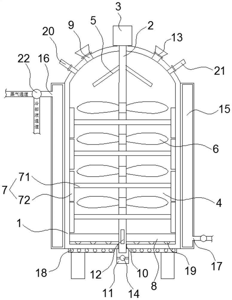
Polyurethane reaction kettle

A reaction kettle and polyurethane technology, which is applied in the field of reaction kettle, can solve the problems that the reaction raw materials cannot be mixed uniformly, the stirring is not uniform and insufficient, and the reaction raw materials are highly viscous, so as to improve the efficiency and the quality of the finished product, prevent insufficient reaction, and automatically control The effect of reaction temperature

Pending Publication Date: 2020-09-22
QINGYUAN FANYI POLYURETHANE CO LTD
View PDF0 Cites 1 Cited by
  • Summary
  • Abstract
  • Description
  • Claims
  • Application Information

AI Technical Summary

Problems solved by technology

[0002] Polyurethane material is the abbreviation of polyurethane. Polyurethane is a polymer material with high strength, tear resistance and wear resistance. It is widely used in light industry, chemical industry, electronics and textile because of its excellent performance. , medical, construction, building materials, automobiles, national defense, aerospace, aviation and other fields, in the existing production process of polyurethane, the polyurethane is usually placed in the reaction device for reaction, and a simple stirring rod is used for stirring, but when mixing When there are many materials, there is the problem of uneven and insufficient stirring, especially when the reaction raw materials are agglomerated, the reaction raw materials cannot be dispersed, and the quality of the finished product is low. However, the reaction speed cannot be changed in time according to the reaction, resulting in low reaction efficiency and low quality of the finished product. , and due to the high viscosity of the reaction raw materials, the reaction raw materials are easily attached to the inner wall of the reaction device, so that the reaction raw materials cannot be mixed evenly, and the waste of the reaction raw materials can also be caused

Method used


Image

  • Polyurethane reaction kettle

Examples


Embodiment Construction

[0018] The specific implementation manners of the present invention will be further described in detail below in conjunction with the accompanying drawings and embodiments. The following examples are used to illustrate the present invention, but are not intended to limit the scope of the present invention.

[0019] In describing the present invention, it should be understood that the terms "center", "longitudinal", "transverse", "upper", "lower", "front", "rear", "left", " The orientation or positional relationship indicated by "right", "vertical", "horizontal", "top", "bottom", "inner", "outer", etc. is based on the orientation or positional relationship shown in the drawings, and is only for the convenience of description The present invention and simplified description do not indicate or imply that the device or element referred to must have a specific orientation, be constructed and operate in a specific orientation, and thus should not be construed as limiting the present...


PUM


Abstract

The invention relates to the technical field of reaction kettles, and discloses a polyurethane reaction kettle. The reaction kettle comprises a kettle body, a rotating shaft, a motor and a controller,a cavity is arranged in the kettle body, the motor is arranged in kettle body, the motor and rotating shaft are in connection, the rotating shaft is provided with a material dispersing annular plate,the rotating shaft is provided with stirring blades and scraping plates alternately at intervals, a stirring rod in contact with the bottom of the cavity is arranged at the lower part of the rotatingshaft, the top of the kettle body is provided with a feeding hole positioned above the material dispersing annular plate, a discharge hole is formed in the bottom of the kettle body, a discharge pipeis connected to the discharge hole, the bottom end of the rotating shaft extends into the discharge pipe, the rotating shaft is of a hollow structure, a material passing port for communicating the cavity with the discharge pipe is formed in the lower portion of the rotating shaft, a temperature control mechanism is arranged on the kettle body, a temperature sensor is arranged on the cavity, and the controller is electrically connected to the motor, a feed valve, a discharge valve, the temperature control mechanism and the temperature sensor respectively. The reaction kettle has the advantagesthat reaction raw materials can be fully mixed, the reaction temperature can be automatically controlled, the reaction efficiency is high, and the finished product quality is high.

Description

technical field [0001] The invention relates to the technical field of reactors, in particular to a polyurethane reactor. Background technique [0002] Polyurethane material is the abbreviation of polyurethane. Polyurethane is a polymer material with high strength, tear resistance and wear resistance. It is widely used in light industry, chemical industry, electronics and textile because of its excellent performance. , medical, construction, building materials, automobiles, national defense, aerospace, aviation and other fields, in the existing production process of polyurethane, the polyurethane is usually placed in the reaction device for reaction, and a simple stirring rod is used for stirring, but when mixing When there are many materials, there is the problem of uneven and insufficient stirring, especially when the reaction raw materials are agglomerated, the reaction raw materials cannot be dispersed, and the quality of the finished product is low. However, the reactio...

Claims


Application Information

Patent Timeline
Patent Type & Authority Applications(China)
IPC IPC(8): B01J19/18B01J19/00B08B9/087
CPCB01J19/0013B01J19/0053B01J19/0066B01J19/18B01J2219/00094B01J2219/00135B08B9/087
Inventor 唐定凯
Owner QINGYUAN FANYI POLYURETHANE CO LTD
Why Eureka
Try Eureka