Thin-film battery discharging device

A thin-film battery and bottom plate technology, which is applied to circuits, electrical components, transportation and packaging, etc., can solve the problems of different sizes of thin-film batteries and affect the processing of thin-film batteries, and achieve the effects of easy adjustment, improved production efficiency, and prevent damage

Active Publication Date: 2020-09-22
扬州高强电子有限公司
View PDF4 Cites 5 Cited by
  • Summary
  • Abstract
  • Description
  • Claims
  • Application Information

AI Technical Summary

Problems solved by technology

[0003] During the production process of solar thin-film batteries, it is necessary to cut the whole solar thin-film battery into the required size according to the production requirements. After cutting the thin-film batteries, the cut thin-film batteries need to be transported. The existing transport equipment generally uses fixed-width However, due to the different sizes of the cut thin film batteries, when the conveyor belt transports the thin film batteries, it is easy to make the thin film batteries pile up together, or multiple thin film batteries are transported side by side, which affects the processing equipment in the next step. processing

Method used


Image

  • Thin-film battery discharging device
  • Thin-film battery discharging device
  • Thin-film battery discharging device

Examples


Embodiment Construction

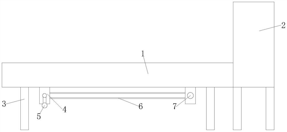
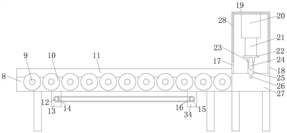
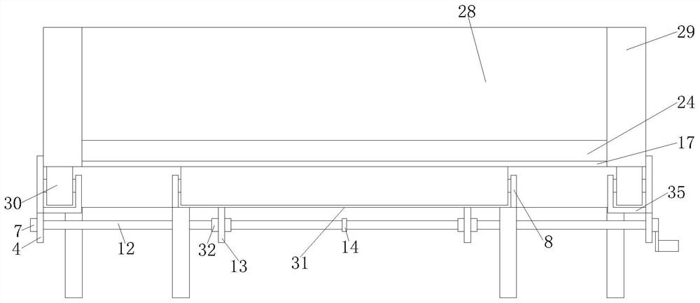
[0026] Such as Figure 1-5 As shown, the present invention provides a kind of technical scheme:

[0027]A thin-film battery unloading device, including a transmission mechanism 1 and a cutting mechanism 2. The thin-film battery is cut by the cutting mechanism 2 and sent to the transmission mechanism 1 for delivery to the next process. The transmission mechanism 1 is provided with a bottom plate 31, which is convenient for installation Fixed ear seat one 13 and fixed ear seat two 34, the front and rear ends of the upper surface of the base plate 31 are fixedly connected with a roller frame 8, and the transmission roller 10 is fixed by the roller frame 8, and a support frame 3 is fixedly installed around the bottom of the base plate 31 to support The frame 3 provides support for the entire transmission mechanism 1, one side of the bottom of the bottom plate 31 is fixedly connected with a fixed ear seat 13, and the other side of the bottom of the bottom plate 31 is fixedly connec...


PUM


Abstract

The invention relates to the technical field of solar thin-film battery manufacturing equipment. The invention further discloses a thin-film battery discharging device. The device comprises a conveying mechanism and a cutting mechanism, the conveying mechanism is provided with a bottom plate. A roller frame is fixedly connected to the front end and the rear end of the upper surface of the bottom plate. A supporting frame is fixedly installed inthe periphery of the bottom of the bottom plate. One side of the bottom of the bottom plate is fixedly connected with a fixed lug I; the other side of the bottom of the bottom plate is fixedly connected with a fixed lug II; the roller frame is movably connected with a roller shaft; a conveying roller is fixedly mounted on the roller shaft; the fixedlug I is movably connected with a main threaded rod; the fixed lug II is movably connected with a driven threaded rod; and a main chain wheel is fixedly installed in the middle of the main threaded rod, the main threaded rod is fixedly connected with limiting blocks located atthe two sides of the fixed lug I, and the main threaded rod is in threaded connection with a movable lug. The problems thatin the background art, conveying is inconvenient, thin-film batteries are prone to stacking and side-by-side conveying, and the next procedure is affected are solved.

Description

technical field [0001] The invention relates to the technical field of solar thin-film battery manufacturing equipment, in particular to a thin-film battery unloading device. Background technique [0002] Thin-film battery, as the name implies, is to prepare a thin film into a solar cell. It uses very little silicon, which makes it easier to reduce costs. At the same time, it is not only a high-efficiency energy product, but also a new type of building material, which is easier to perfectly integrate with buildings. Under the background of continuous shortage of silicon raw materials in the international market, thin-film solar cells have become a new trend and new hotspot in the development of the international photovoltaic market. The principle of thin-film battery power generation is similar to that of crystalline silicon. When sunlight irradiates the battery, the battery absorbs light energy to generate photogenerated electron-hole pairs. Under the action of the built-in...

Claims


Application Information

Patent Timeline
Patent Type & Authority Applications(China)
IPC IPC(8): H01L31/18H01L21/677B26D1/08B26D7/22
CPCH01L31/18H01L21/67706B26D1/085B26D7/22Y02P70/50
Inventor 邱泽亮
Owner 扬州高强电子有限公司
Why Eureka
Try Eureka