
LTCC filtering medium resonant antenna

A technology of dielectric resonant antenna and dielectric resonant cavity, which is applied to antennas, resonators, antenna arrays, etc., can solve problems such as complex manufacturing process, large antenna size, and antenna performance impact, and achieve increased gain, improved directivity, and reduced attenuation Effect

Inactive Publication Date: 2020-09-22
宿迁博翔教育科技有限公司
View PDF8 Cites 2 Cited by
  • Summary
  • Abstract
  • Description
  • Claims
  • Application Information

AI Technical Summary

Problems solved by technology

[0003] However, in the existing technology, either the size of the antenna is relatively large, or the manufacturing process is complicated, and if the feeding antenna and the reflected wave are on the same side, the performance of the antenna will be affected

Method used


Image

  • LTCC filtering medium resonant antenna
  • LTCC filtering medium resonant antenna
  • LTCC filtering medium resonant antenna

Examples


Embodiment Construction

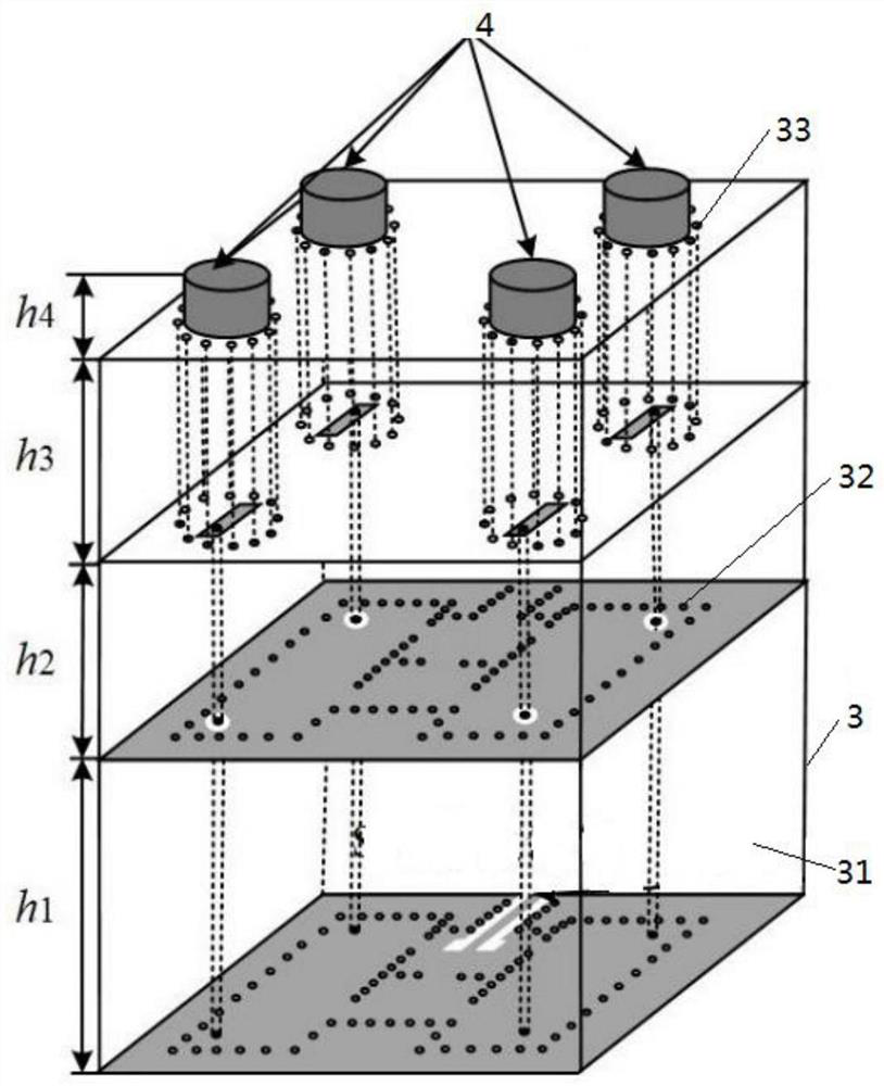
[0030] refer to Figures 1 to 6 As shown, the structural characteristics of this LTCC filter dielectric resonant antenna are described in detail as follows:

[0031] Such as figure 1 As shown, a LTCC filter dielectric antenna includes a low-temperature co-fired ceramic substrate (LTCC) 3 and a dielectric resonator 4, and the low-temperature co-fired ceramic substrate (LTCC) 3 adopts a three-layer substrate, wherein the substrate integrates a waveguide The resonance cavity (SIW) 31 is located at the bottom; the dielectric resonator 4 is set as a 2×2 array antenna composed of four cylindrical dielectric resonators, and the dielectric resonator 4 is fixed on a low temperature co-fired ceramic substrate (LTCC) 3 the top of. Compared with the planar SIW cavity, the volume of the LTCC filter dielectric antenna is greatly reduced.

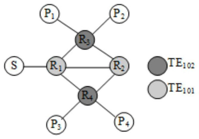
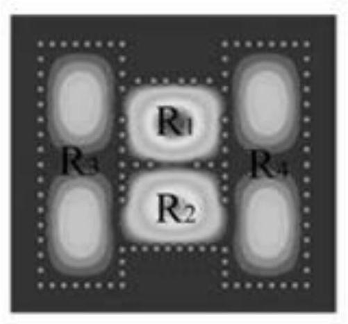
[0032] Among them, the cavity in the middle works under the dominant mode TE101, and the left and right sides of the cavity work under the high-order ...


PUM

PropertyMeasurementUnit
Heightaaaaaaaaaa

Abstract

The invention discloses an LTCC filtering dielectric resonant antenna, and the antenna comprises a low-temperature co-fired ceramic substrate and a dielectric resonator; the low-temperature co-fired ceramic substrate adopts three layers of substrates, and an integrated waveguide resonant cavity power divider based on an LTCC substrate is located at the bottommost layer; the dielectric resonator isa 2*2 array antenna, and the dielectric resonator is fixedly arranged at the top of the low-temperature co-fired ceramic substrate; the epsilon r of the low-temperature co-fired ceramic substrate is5.9, and the loss tangent is 0.0023; the thicknesses of the three layers of cavities of the low-temperature co-fired ceramic substrate are sequentially as follows from bottom to top: h1 = 0.58 mm, h2= 0.19 mm and h3 = 0.38 mm, and the thickness of the metal layer of the low-temperature co-fired ceramic substrate is 10 [mu]m. According to the filtering medium resonant antenna, the LTCC three-dimensional integration technology is fully utilized, the size is effectively reduced, the overall size is 12mm, 12mm and 2.4 mm, and the filtering medium resonant antenna is suitable for being applied toa 5G wireless communication system and a feed source of a transmission and reflection antenna array.

Description

technical field [0001] The invention relates to the technical field of antennas, in particular to an LTCC filter dielectric resonant antenna. Background technique [0002] With the development of wireless communication technology and the requirements of communication systems, high-gain antennas have aroused the interest of researchers. In the 1980s, researchers at the University of Houston published the first paper on dielectric resonant antennas, which made dielectric resonators an option for antenna design. The principle of the resonant cavity of the dielectric resonator and the metal waveguide structure is similar, so according to the basic theory of the resonant cavity, on the electric wall of the metal waveguide resonant cavity, the tangential component of the electric field and the normal phase component of the magnetic field are both zero, incident to the electric wall The electromagnetic wave on the surface will be completely reflected back, so when a closed cavity ...

Claims


Application Information

Patent Timeline
IPC IPC(8): H01Q1/50H01P7/10H01Q1/38H01Q21/00
CPCH01P7/105H01Q1/38H01Q1/50H01Q21/00
Inventor 张祥军魏泽华陈小二
Owner 宿迁博翔教育科技有限公司
Learn More