Planetary grinding device and grinding method for planar optical element

A technology for optical components and grinding devices, which is applied in the direction of grinding devices, optical surface grinders, grinding machine tools, etc., can solve the problems of reduced processing accuracy, small removal amount, and large removal amount, so as to ensure contact stability, avoid direct contact, The effect of improving processing efficiency

Active Publication Date: 2020-09-25
XI AN JIAOTONG UNIV
View PDF6 Cites 1 Cited by
  • Summary
  • Abstract
  • Description
  • Claims
  • Application Information

AI Technical Summary

Problems solved by technology

Among them, grinding, as a process between grinding and polishing, plays a link between the preceding and the following. The flatness of the components during the grinding process plays an important role in the subsequent polishing and application of the components. Poor flatness will result in low efficiency of subsequent polishing and reduce the optical quality. For the imaging and light-gathering quality of components, the current grinding methods for small optical glass mainly adopt manual grinding method and mechanical grinding method, and the glass sample is held in hand, and the surface is contacted with a grinding disc for grinding; this method has the following drawbacks: 1. It is difficult to ensure that the surface of the workpiece is always parallel to the surface of the grinding disc when holding the workpiece, and one end will be inclined, which will cause a large amount of removal at the lower part of the inclination of the workpiece, and a small amount of removal at the other part, resulting in poor flatness; After t...

Method used


Image

  • Planetary grinding device and grinding method for planar optical element
  • Planetary grinding device and grinding method for planar optical element
  • Planetary grinding device and grinding method for planar optical element

Examples


Embodiment Construction

[0034] The present invention is described in further detail below in conjunction with accompanying drawing:

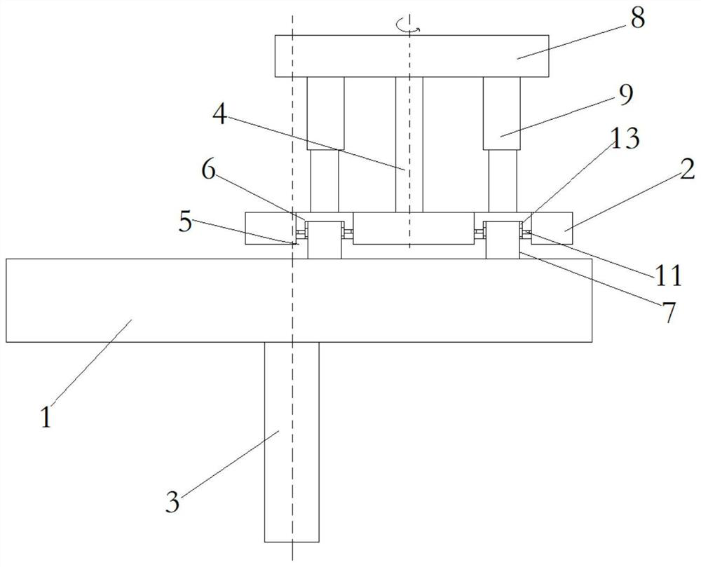
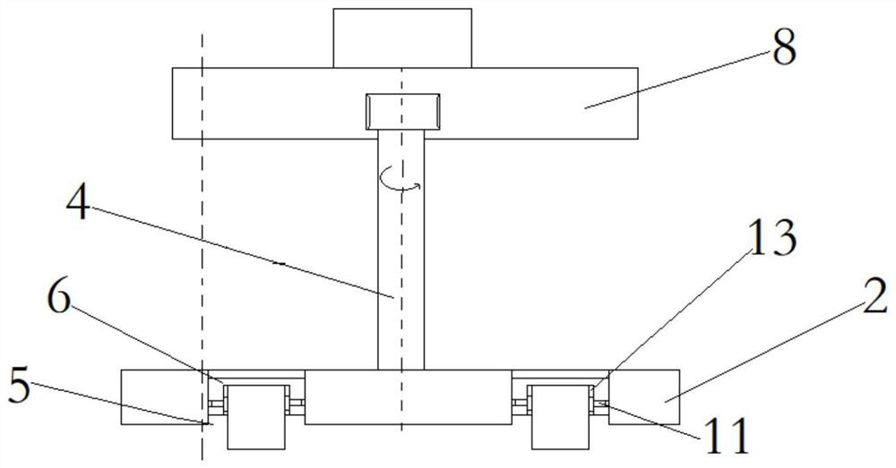
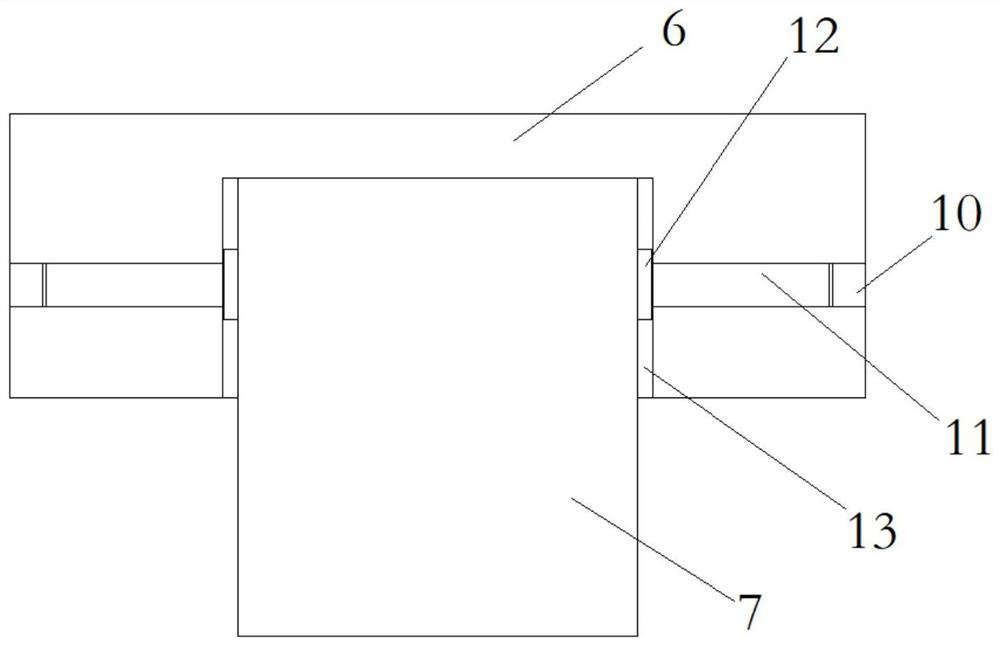
[0035] Such as figure 1As shown, a planetary grinding device for a plane optical element of the present invention includes a grinding table 1 and a workpiece disc 2, the lower end of the grinding table 1 is provided with a grinding disc spindle 3 for driving the grinding table 1 to rotate, and the workpiece disc 2 is arranged on the grinding table 1 The upper end, the lower end surface of the workpiece disc 2 is parallel to the upper end surface of the grinding table 1, the upper end of the workpiece disc 2 is fixed with the workpiece disc drive shaft 4 for driving the workpiece disc 2 to rotate, the rotation center of the workpiece disc drive shaft 4 and the rotation of the grinding disc spindle 3 The center does not coincide; the workpiece plate 2 is provided with a plurality of fixture positioning holes 5, and the plurality of fixture positioning holes 5 are arrayed...


PUM


Abstract

The invention discloses a planetary grinding device and a grinding method for a planar optical element. According to the planetary grinding device and method for the planar optical element, the lowerend face of a workpiece disc and the upper end face of a grinding table are arranged in parallel, the grinding table and the workpiece disc can rotate in a mutually non-coaxial mode, a plurality of clamp positioning holes are formed in the workpiece disc, the multiple clamp positioning holes are circumferentially arrayed with the axis of a driving shaft of the workpiece disc as the center, the to-be-machined optical element is clamped through a clamp, the to-be-ground end face of the to-be-machined optical element makes contact with the upper grinding end face after being limited through the workpiece disc, and finally the pressure between the to-be-machined optical element and the grinding table is adjusted through a pressure applying device, and the contact stability between the to-be-machined optical element and the grinding table is ensured. The device is simple in structure, the grinding speed of the planar optical element is greatly increased through mutual rotation of the grinding disc and the workpiece disc in a planetary motion mode, the same pressure is kept in real time through the pressure applying device in the grinding process, the flatness of workpiece machining is guaranteed, and the machining efficiency of the whole machining technology is improved.

Description

technical field [0001] The invention relates to the field of precision machining, in particular to a planetary grinding device and a grinding method for a plane optical element. Background technique [0002] Optical glass has excellent properties such as high strength, high hardness, and high wear resistance, and is widely used in defense and civilian fields such as electronics and machinery. Optical glass goes through grinding, grinding, polishing, coating and other processes from blank to forming. Among them, grinding, as a process between grinding and polishing, plays a link between the preceding and the following. The flatness of the components during the grinding process plays an important role in the subsequent polishing and application of the components. Poor flatness will result in low efficiency of subsequent polishing and reduce the optical quality. For the imaging and light-gathering quality of components, the current grinding methods for small optical glass main...

Claims


Application Information

Patent Timeline
IPC IPC(8): B24B37/00B24B37/11B24B37/27B24B37/34B24B13/00B24B13/005B24B13/01B24B49/12B24B1/00
CPCB24B1/00B24B13/00B24B13/005B24B13/01B24B37/00B24B37/11B24B37/27B24B37/34B24B41/007B24B49/12
Inventor 蒋庄德刘剑锋孙林李常胜林启敬段端志方续东
Owner XI AN JIAOTONG UNIV
Why Eureka
Try Eureka