
Low-temperature strong-heat air source heat pump system

A technology of hot air and source heat pumps, which is applied in climate sustainability, lighting and heating equipment, and compressors with reversible cycles, etc. It can solve problems such as high exhaust temperature, failure to start and run normally, and overheated operation.

Pending Publication Date: 2020-09-25
顿汉布什(中国)工业有限公司
View PDF0 Cites 5 Cited by
  • Summary
  • Abstract
  • Description
  • Claims
  • Application Information

AI Technical Summary

Problems solved by technology

[0007] (1) Contradiction between heat supply and demand: the heat demanded by the building is linearly inversely proportional to the outer ring temperature, the outer ring temperature is low, the heat demand is large, and the heat loss of conventional air source heat pumps is obvious;
[0008] (2) Limitations: in severe cold areas, conventional air source heat pump systems cannot start and run normally when the ambient temperature is ≤-15°C, the ambient temperature is ≤-20°C, and the COPH is difficult to exceed 2.0 (the output water temperature is 41°C);
[0009] (3) Under the condition of high pressure ratio, the discharge temperature of the compressor keeps rising, there is a risk of overheating operation in the compression, the compressor is poorly lubricated, which affects the service life of the compressor, and the discharge temperature is high, which cannot be effectively controlled by means and methods put it within the reliable range

Method used


Image

  • Low-temperature strong-heat air source heat pump system
  • Low-temperature strong-heat air source heat pump system
  • Low-temperature strong-heat air source heat pump system

Examples


Embodiment Construction

[0044] The principles and features of the present invention are described below in conjunction with the accompanying drawings, and the examples given are only used to explain the present invention, and are not intended to limit the scope of the present invention.

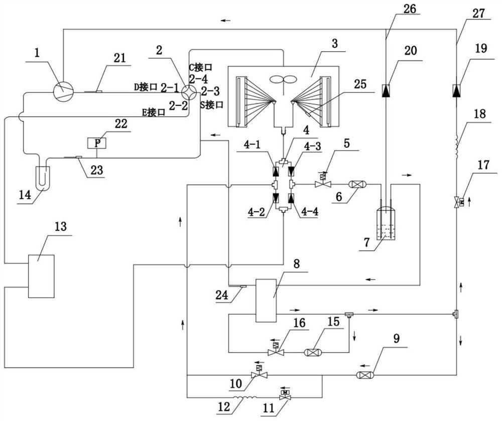
[0045] A kind of low temperature strong hot air source heat pump system (see Figure 1 to Figure 5 ), including compressor 1, four-way reversing valve 2, air-cooled condenser 3, check valve assembly 4, flasher 7, economizer 8, water side heat exchanger 13 and gas-liquid separator 14;

[0046] The suction port of the compressor 1 is connected to the gas-liquid separator 14, and the exhaust port is connected to the air-cooled condenser 3 or the water-side heat exchanger 13 through the D interface 2-1 of the four-way reversing valve 2. The air supply port of the compressor 1 is connected with the air supply circuit 26 and the liquid injection circuit 27; the coil of the compressor 1 is cooled by the suction working flu...


PUM

PropertyMeasurementUnit
Diameteraaaaaaaaaa

Abstract

The invention provides a low-temperature strong-heat air source heat pump system. The system comprises a compressor, an air-cooled condenser, a one-way valve assembly, a flash tank, an economizer, a water side heat exchanger and a gas-liquid separator. An air suction port of the compressor is connected with the gas-liquid separator, an exhaust port of the compressor is connected with the air-cooled condenser or the water side heat exchanger through a four-way reversing valve, and an air supplement port of the compressor is connected with an air supplement loop and a liquid spraying loop. The air-cooled condenser is connected with a first-stage throttling electronic expansion valve through the one-way valve assembly; the first-stage throttling electronic expansion valve is connected with the flash tank through a drying filter A; a liquid outlet of the flash tank is connected with a main side inlet of the economizer, and an air supply port of the flash tank is connected with the air supply loop; a main side outlet of the economizer is connected with the liquid spraying loop and a second-stage throttling electronic expansion valve; and the second-stage throttling electronic expansionvalve is connected with the economizer through a drying filter B, and the second-stage throttling electronic expansion valve is connected with the water side heat exchanger or the air-cooled condenserthrough the one-way valve assembly.

Description

technical field [0001] The invention relates to the technical field of heating, ventilating and air conditioning, in particular to a low-temperature strong-heat air source heat pump system. Background technique [0002] The air source heat pump system uses low-grade air as the cold and heat source, uses refrigerant as the working medium, and is composed of four major devices: compressor, evaporator, condenser, and throttling device as the main core components. It is a form of renewable energy utilization system that works to produce cold and hot water. [0003] Nowadays, with the rapid development of the global economy, energy shortages, increased environmental pollution, and global warming have become issues of concern to the world, especially severe challenges faced by the global refrigeration and air-conditioning industry; to achieve efficient use of energy, low-carbon environmental protection, and reduced energy consumption Particularly important. Among them, the air s...

Claims


Application Information

Patent Timeline
IPC IPC(8): F25B13/00F25B41/04F25B41/06F25B49/02
CPCF25B13/00F25B49/02Y02B30/70
Inventor 李衍基莫军民滕轩王世超
Owner 顿汉布什(中国)工业有限公司
Learn More