
Optical fiber passive high-voltage cable loop current detection system and method

A high-voltage cable and detection system technology, applied in the field of high-voltage electricity and optical fiber communication, can solve the problems of high cost, difficult communication, difficult communication in underground wells, etc., and achieve the effect of stable performance and simple detection method

Pending Publication Date: 2020-09-25
ZHEJIANG NEW TUWEI ELECTRONICS TECH CO LTD
View PDF1 Cites 1 Cited by
  • Summary
  • Abstract
  • Description
  • Claims
  • Application Information

AI Technical Summary

Problems solved by technology

[0007] The purpose of the present invention is to provide a fiber optic passive high-voltage cable circulation detection system and method to solve the problems in the prior art that the high-voltage cable circulation detection requires external power supply, communication difficulties require GRS communication, and the underground shaft is difficult to communicate and the cost is high. many difficulties

Method used


Image

  • Optical fiber passive high-voltage cable loop current detection system and method
  • Optical fiber passive high-voltage cable loop current detection system and method
  • Optical fiber passive high-voltage cable loop current detection system and method

Examples


Embodiment Construction

[0035] The following will clearly and completely describe the technical solutions in the embodiments of the present invention with reference to the accompanying drawings in the embodiments of the present invention. Obviously, the described embodiments are only some, not all, embodiments of the present invention. Based on the embodiments of the present invention, all other embodiments obtained by persons of ordinary skill in the art without making creative efforts belong to the protection scope of the present invention.

[0036] In order to overcome the technical defects in the prior art of high-voltage cable circulating current detection, an embodiment of the present invention proposes a fiber optic passive high-voltage cable circulating current detection system and method. It solves many difficulties existing in the prior art, such as external power supply required for high-voltage cable circulation detection, GRS communication required for communication difficulties, difficul...


PUM


Abstract

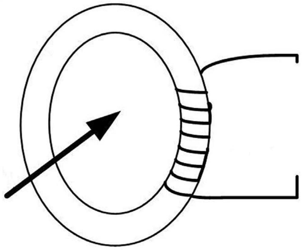
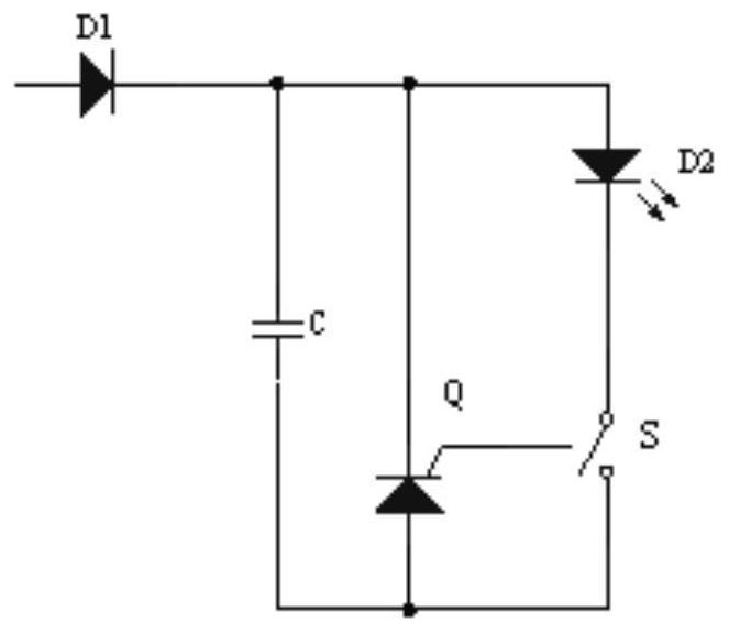
The invention relates to an optical fiber passive high-voltage cable loop current detection system and method. The detection system comprises a loop current detection unit, a light emitting control unit, an optical fiber module, a light detection unit and a loop current calculation unit. The loop current detection unit can gather the mutual inductance energy of the high-voltage loop current into acapacitor C of the light emitting control unit; after the light detection unit detects a light signal, and then sends a pulse signal; the loop current calculation unit has a timing function and can accurately count pulse time of two times; the loop current calculation unit converts time t into a current I by using a formula I = U*C / t; the loop current calculation unit supports an optical fiber, the Ethernet and the GPRS to transmit data to a server; and the light detection unit detects the light signal, calculates the time of two light emitting point pulses through the loop current calculation unit, and calculates the corresponding armored loop current.

Description

technical field [0001] The invention belongs to the fields of high voltage electricity and optical fiber communication, and in particular relates to an optical fiber passive high voltage cable circulation detection system and method. Background technique [0002] In the prior art, the Chinese utility model patent with the notification number CN208432655U provides a high-voltage transmission cable circular current synchronous detection device. A metal sheath current monitor is respectively connected to both ends of the high-voltage transmission cable that needs circulating current detection. A trigger device is set in the middle of the sheath current monitor. The distance between the trigger device and the two metal sheath current monitors is equal, and the trigger device sends acquisition signals to the two metal sheath current monitors at the same time. Since the acquisition signals come from the same One trigger device and two metal sheath current monitors realize the simu...

Claims


Application Information

Patent Timeline
Patent Type & Authority Applications(China)
IPC IPC(8): G01R19/00G01R31/08
CPCG01R19/0092G01R31/083
Inventor 孙宇东袁康张振飞
Owner ZHEJIANG NEW TUWEI ELECTRONICS TECH CO LTD
Learn More