Saturable absorber mode locking method and saturable absorber mode locking device

A saturable absorption and mode-locking technology, applied to laser components, lasers, electrical components, etc., can solve the problems of reducing thermal damage threshold, material mechanical damage, large loss, etc., and achieve suppression of mode competition, interaction balance, insertion The effect of low loss

Inactive Publication Date: 2020-09-25
XI'AN INST OF OPTICS & FINE MECHANICS - CHINESE ACAD OF SCI
View PDF2 Cites 0 Cited by
  • Summary
  • Abstract
  • Description
  • Claims
  • Application Information

AI Technical Summary

Problems solved by technology

At present, in order to realize this kind of saturable absorber device, there are mainly two structural design schemes: first, the saturable absorbing material is made into a thin film, which is placed between two optical fiber jumper connectors or between the end face of the optical fiber and the Between the mirrors, this structural design has the following problems: it destroys the all-fiber structure; it is easy to cause mechanical damage to the material; the laser directly acts on the saturable absorbing material and the action area is small, which reduces the thermal damage threshold and makes it difficult to achieve high-quality locking. mode pulse and the device is easily damaged
The micro-nano optical fiber used in saturable absorber devices mainly includes D-shaped optical fiber and side-polished optical fiber. The production of this type of optical fiber requires complex processes and expensive equipment. It is difficult to weld with ordinary single-mode optical fiber in fiber lasers and the loss is generally large. , the proportion of light passing through the evanescent field and material effects is difficult to precisely control and regulate
For tapered fiber, the core diameter of the fiber at the tapered place is very thin and easy to damage, which is not conducive to practical application

Method used


Image

  • Saturable absorber mode locking method and saturable absorber mode locking device
  • Saturable absorber mode locking method and saturable absorber mode locking device

Examples


Embodiment Construction

[0022] The content of the present invention will be further described in detail below in conjunction with the accompanying drawings and specific embodiments.

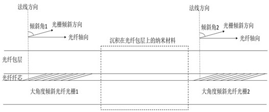
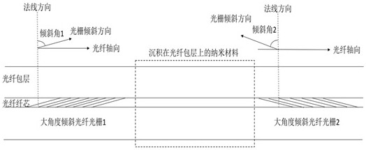
[0023] The invention provides a scheme for realizing a saturable absorber mode-locked device by using a pair of large-angle inclined fiber gratings, which can effectively improve multiple performances of the saturable absorber device, and then realize a stable ultrashort pulse mode-locked fiber laser, Advancing the development of ultrafast fiber laser technology.

[0024] Such as figure 1 As shown, the saturable absorber mode-locking device based on large-angle tilted fiber gratings includes the first large-angle tilted fiber grating and the second large-angle tilted fiber grating connected in sequence along the light transmission direction, and the first large-angle tilted fiber The saturable absorbing material can be deposited or coated on the fiber cladding of the connecting area between the grating and the second l...


PUM

PropertyMeasurementUnit
angleaaaaaaaaaa

Abstract

The invention provides a saturable absorber mode locking method and a saturable absorber mode locking device. According to the present invention, the interaction between the light and a saturable absorption material is realized by utilizing a pair of large-angle tilted fiber gratings, the defects of the existing saturable absorber mode-locking device are overcome, the high-performance saturable absorber mode-locking device is realized, and the development of an ultrafast fiber laser technology is promoted. The saturable absorber mode locking device is based on a large-angle tilted fiber bragggrating, comprises a first large-angle tilted fiber bragg grating and a second large-angle tilted fiber bragg grating which are sequentially connected in the light transmission direction, and the saturable absorption material is deposited or coated on the optical fiber cladding of the connection area of the first large-angle tilted fiber bragg grating and the second large-angle tilted fiber bragggrating, wherein the tilt angle of the first large-angle tilted fiber bragg grating and the tilt angle of the second large-angle tilted fiber bragg grating are 66-89 degrees.

Description

technical field [0001] The invention relates to the field of optical fiber devices and fiber lasers, in particular to a saturable absorber mode-locking method and a saturable absorber mode-locking device, which is a saturable absorber mode-locking device utilizing the mode coupling characteristics of a large-angle tilted fiber grating Mode devices can improve the performance of traditional mode-locked devices and can be applied to ultrashort pulse fiber lasers. Background technique [0002] Fiber laser has become an important development direction in the field of laser technology with unique technical advantages such as high beam quality, high efficiency, high integration, and high reliability. Among them, the ultrashort pulse fiber laser has the remarkable characteristics of narrow pulse width, high repetition frequency, high peak power, wide spectral range, etc. application and huge market value. [0003] Mode-locking technology is the most efficient and concise way to a...

Claims


Application Information

Patent Timeline
Patent Type & Authority Applications(China)
IPC IPC(8): H01S3/11H01S3/067
CPCH01S3/0675H01S3/1115
Inventor 赵卫王屹山王虎山张伟胡晓鸿张挺赵凤艳周凯明
Owner XI'AN INST OF OPTICS & FINE MECHANICS - CHINESE ACAD OF SCI
Why Eureka
Try Eureka