CMOS power amplifier and radio frequency module thereof

A power amplifier and power amplification technology, applied in power amplifiers, high-frequency amplifiers, etc., can solve the problems of limited improvement, output signal distortion, and adverse effects of linearity, and achieve the effect of improving linearity.

Pending Publication Date: 2020-09-25
SHANGHAI PINGSHENG MICRO CORP
View PDF6 Cites 5 Cited by
  • Summary
  • Abstract
  • Description
  • Claims
  • Application Information

AI Technical Summary

Problems solved by technology

[0003] At present, CMOS power amplifiers cannot provide large output power due to their poor voltage resistance, and their nonlinear characteristics make their harmonics intermodulate with other order harmonics at high frequencies, resulting in output signal distortion.
[0004] In the prior art, the linearity and output power can be improved by increasing the bias current and bias voltage, but the efficiency will be reduced, and the degree of improvement is limited
Or by increasing the area of ​​the output tube, it is beneficial to increase the output power, but the increase in the size of the output tube will inevitably increase the parasitic capacitance, which will also increase the adverse impact on linearity, and will lead to a decrease in efficiency and an increase in cost

Method used


Image

  • CMOS power amplifier and radio frequency module thereof
  • CMOS power amplifier and radio frequency module thereof
  • CMOS power amplifier and radio frequency module thereof

Examples


Embodiment Construction

[0026] Hereinafter, the present invention will be described in more detail with reference to the accompanying drawings. In the various figures, identical elements are indicated with similar reference numerals. For the sake of clarity, various parts in the drawings have not been drawn to scale. Also, some well-known parts may not be shown in the drawings.

[0027] In the following, many specific details of the present invention are described, such as device structures, materials, dimensions, processing techniques and techniques, for a clearer understanding of the present invention. However, the invention may be practiced without these specific details, as will be understood by those skilled in the art.

[0028] It should be understood that the connection / coupling of A and B in the embodiment of the present application means that A and B may be connected in series or in parallel, or A and B may be connected through other devices, which is not limited in the embodiment of the p...


PUM


Abstract

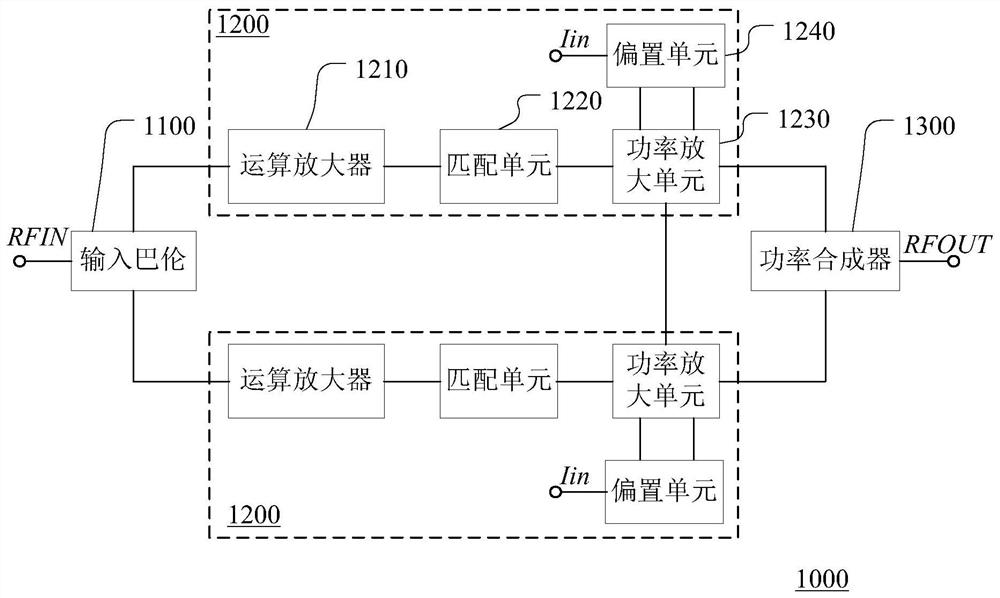
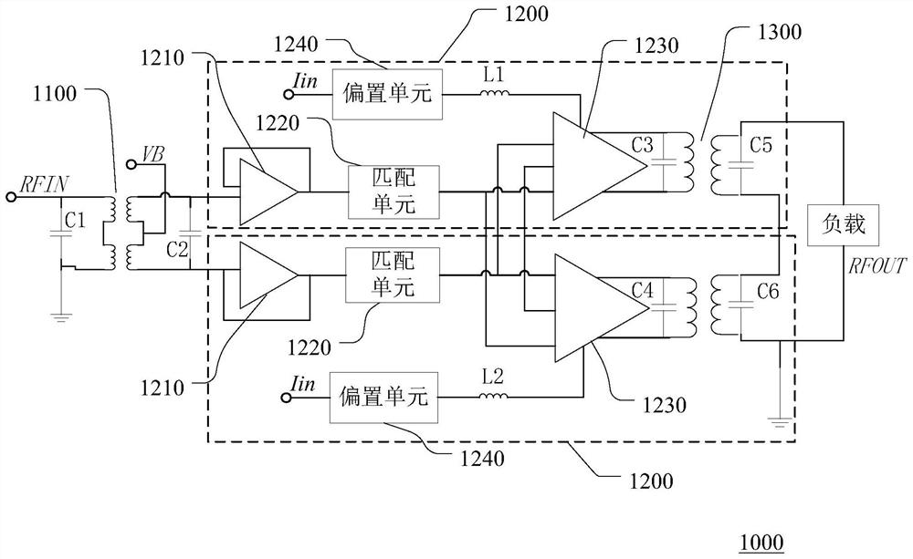
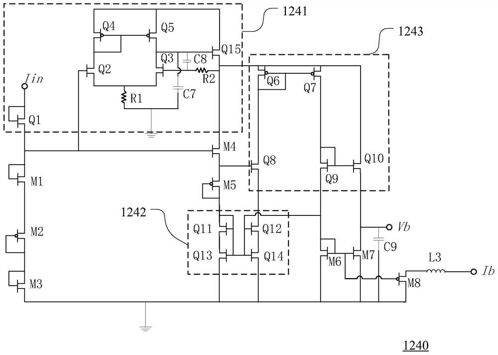
The invention discloses a CMOS (Complementary Metal-Oxide-Semiconductor Transistor) power amplifier. The CMOS power amplifier comprises an input balun which receives a radio frequency input signal andgenerates a first input signal and a second input signal, a power amplification circuit which performs power amplification on the first input signal to generate a first output signal, and performs power amplification on the second input signal to generate a second output signal, and a power combiner which is connected with the power amplification circuit and generates a radio frequency output signal based on the first output signal and the second output signal. The power amplification circuit comprises a power amplification unit and a bias unit, and the bias unit provides bias current for theoutput end of the power amplification unit so as to eliminate a sub-harmonic component generated during power amplification. According to the CMOS power amplifier, a power synthesis technology is adopted, and the output power of the CMOS power amplifier is greatly improved; and the bias unit for generating the bias current is arranged in the power amplification circuit, so that the linearity of the CMOS power amplifier is greatly improved.

Description

technical field [0001] The present invention relates to the technical field of electronic power, and more specifically, relates to a CMOS power amplifier and a radio frequency module thereof. Background technique [0002] With the popularity of portable digital products, in the communication system, the proportion of radio frequency chips is getting higher and higher. As the core component of the radio frequency chip, the power amplifier has low cost and high performance, which has become the goal pursued by those skilled in the art. CMOS (Complementary Metal Oxide Semiconductor, Complementary Metal Oxide Semiconductor) power amplifiers are widely used in radio frequency chips due to their advantages of easy integration and low cost. Especially with the arrival of the fifth generation (5G for short) wireless communication era, CMOS power amplifiers will have greater application space [0003] At present, the CMOS power amplifier cannot provide large output power due to its...

Claims


Application Information

Patent Timeline
Patent Type & Authority Applications(China)
IPC IPC(8): H03F3/20H03F3/189
CPCH03F3/20H03F3/189
Inventor 梁绪亮汪洋
Owner SHANGHAI PINGSHENG MICRO CORP
Why Eureka
Try Eureka