
Automatic vacuum backflow welding equipment adopting contact type temperature control

A technology of vacuum reflow and welding equipment, applied in welding equipment, metal processing equipment, electric heating devices, etc., can solve the problems of heavy cavity cover, inconvenient operation, low heating efficiency, low heating temperature, etc., to achieve easy cleaning and maintenance, heating speed Fast, high heating effect

Pending Publication Date: 2020-09-29
烟台华创智能装备有限公司
View PDF0 Cites 3 Cited by
  • Summary
  • Abstract
  • Description
  • Claims
  • Application Information

AI Technical Summary

Problems solved by technology

[0005] Aiming at the deficiencies in the prior art, the present invention provides an automatic vacuum reflow soldering equipment using contact temperature control to solve the problems of low heating efficiency, uneven heating and low heating temperature in the vacuum reflow soldering equipment in the prior art. The poor welding quality of the product caused by it, and the technical problems that the cavity cover is too heavy and inconvenient to operate

Method used


Image

  • Automatic vacuum backflow welding equipment adopting contact type temperature control
  • Automatic vacuum backflow welding equipment adopting contact type temperature control
  • Automatic vacuum backflow welding equipment adopting contact type temperature control

Examples


Embodiment Construction

[0037] The principles and features of the present invention are described below in conjunction with the accompanying drawings, and the examples given are only used to explain the present invention, and are not intended to limit the scope of the present invention.

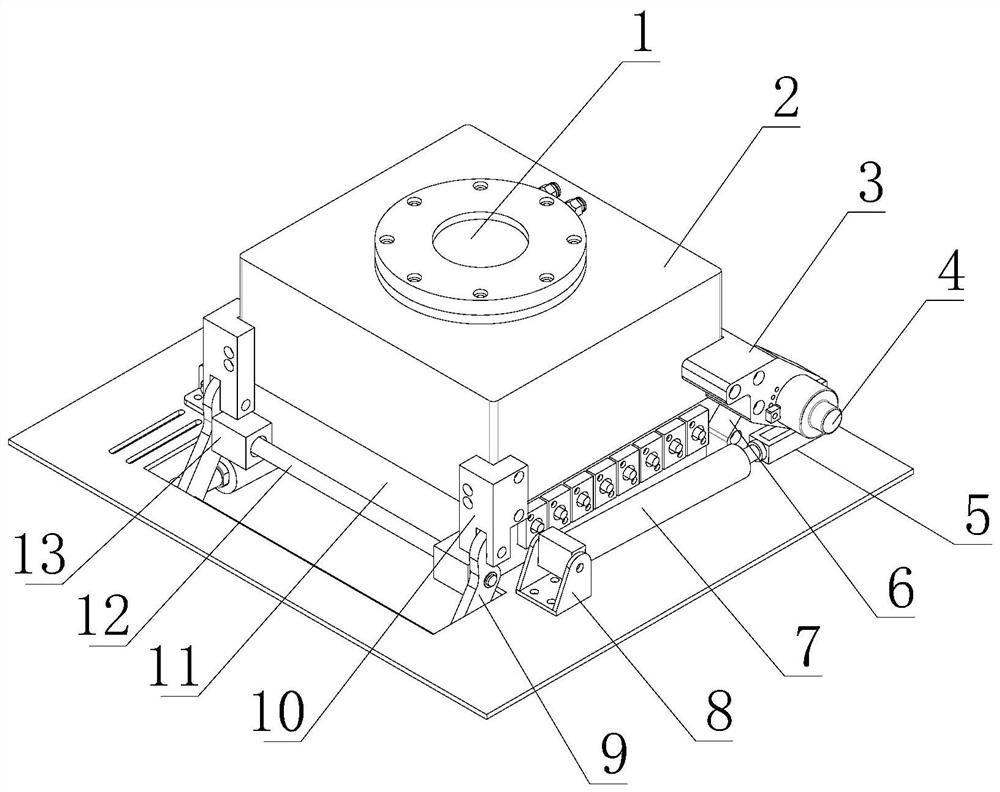
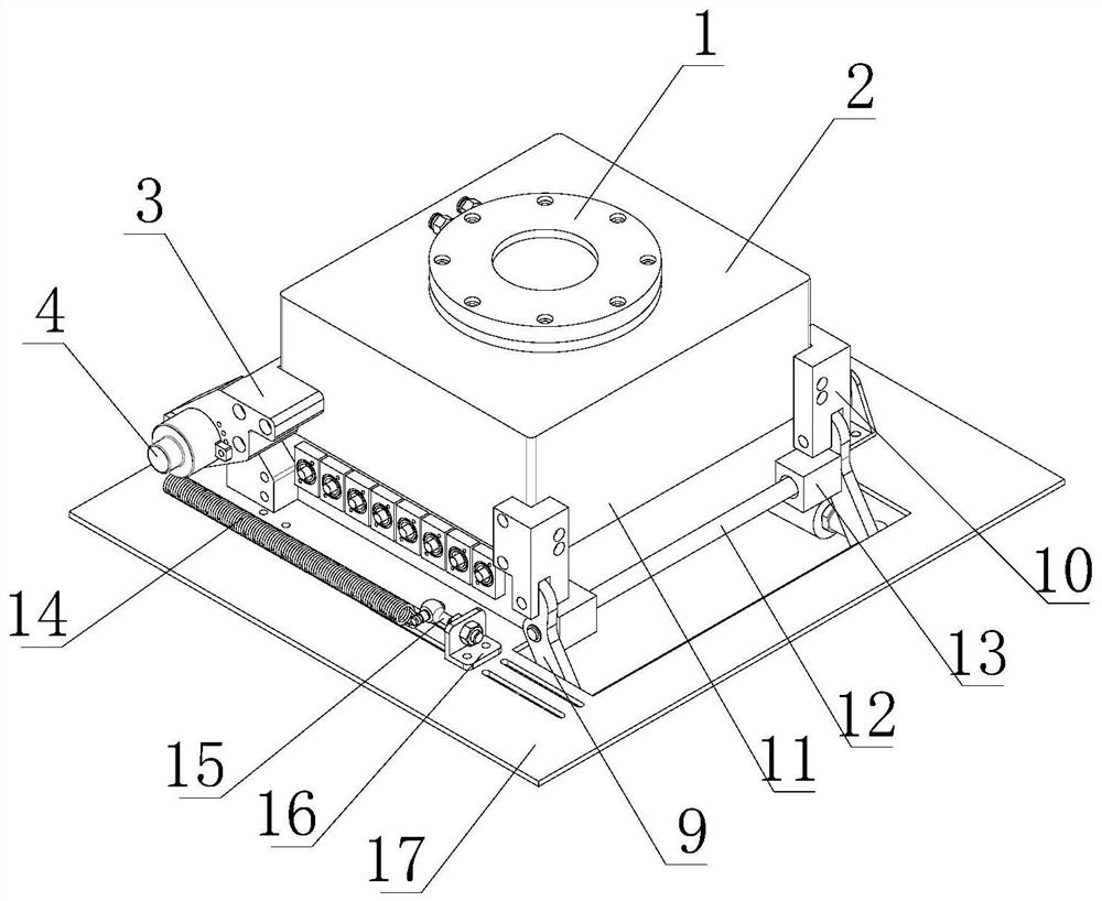
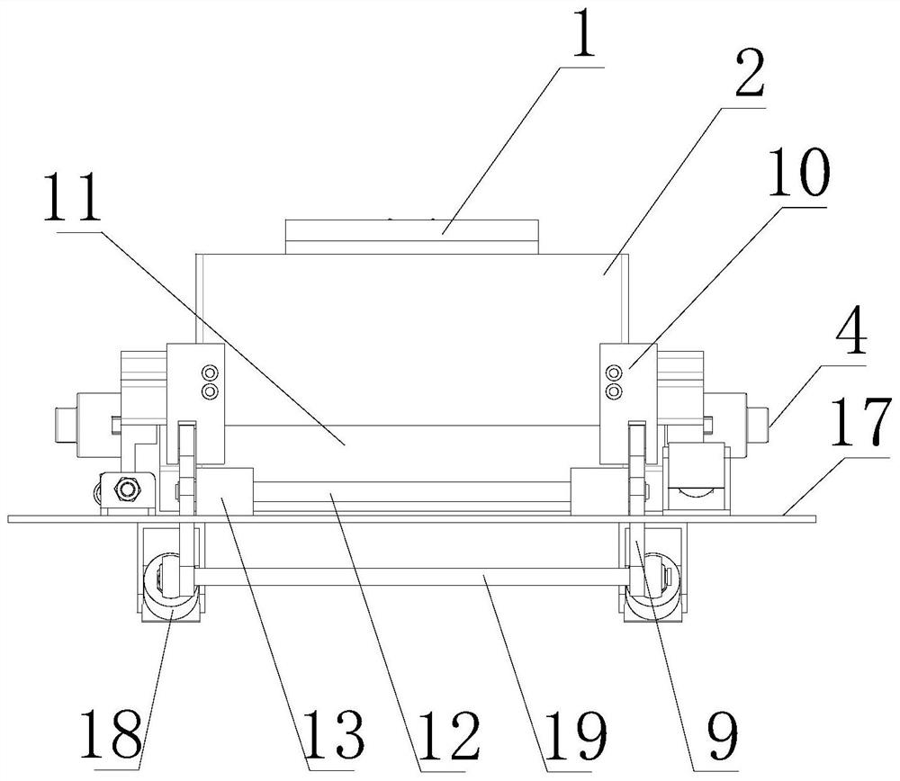
[0038] See attached Figure 1-6 , a kind of automatic vacuum reflow soldering equipment adopting contact temperature control, comprising a heating chamber 11, a chamber cover 2 forming a sealed cavity with the heating chamber 11, several infrared radiation tubes 27 installed inside the heating chamber 11, located in the infrared radiation tube The heating plate 23 above 27, the contact temperature control mechanism, the vacuuming mechanism and the cooling mechanism connected with the heating chamber 11, the heating chamber 11 and the chamber cover 2 are all made of quartz glass, and one end of the chamber cover 2 is hingedly installed in the heating chamber 11, the other end is detachably sealed with the heating cha...


PUM


Abstract

The invention relates to automatic vacuum backflow welding equipment adopting contact type temperature control, and belongs to the technical field of vacuum backflow welding. The automatic vacuum backflow welding equipment adopting contact type temperature control comprises a heating chamber, a cavity cover, infrared radiation tubes, a heating plate located above the infrared radiation tubes, a contact type temperature control mechanism, a vacuumizing mechanism and a cooling mechanism, wherein one end of the cavity cover is hinged to and installed on the heating chamber, and the other end of the cavity cover and the heating chamber are detachably installed in a sealed mode through an automatic opening and closing locking device; a heating cavity is arranged in the heating chamber and internally provided with the multiple infrared radiation tubes; and the contact type temperature control mechanism comprise a main thermocouple and a movable thermocouple, the main thermocouple is installed in the heating cavity and is installed at the bottom of the heating plate in a contact mode, the movable thermocouple is installed on the cavity cover and is installed on the upper surface of the heating plate in a contact mode, and both the main thermocouple and the movable thermocouple are electrically connected with a PID heating controller. The automatic vacuum backflow welding equipment adopting contact type temperature control is used for solving the technical problem of poor product welding quality caused by low heating efficiency, uneven heating and low heating temperature of vacuumreflow welding equipment, and the technical problem that the cavity cover is too heavy to operate.

Description

technical field [0001] The invention relates to an automatic vacuum reflow soldering equipment adopting contact temperature control, belonging to the technical field of vacuum reflow soldering. Background technique [0002] In the context of the rapid development of modern integrated circuits and electronic technology, semiconductor products are more and more widely used. With the improvement of the quality requirements of semiconductor products, especially semiconductor metal packaging devices and semiconductor ceramic packaging devices, traditional reflow soldering Process, welding quality and void rate can no longer meet the quality requirements of semiconductor products. [0003] At present, the traditional vacuum reflow furnace heats the circuit board by using the hot air generated by the filament in the heating box and the hot air circulation. Inside. In order to make the air out of the heating box uniform, there is a metal rectifying plate at the air outlet of the h...

Claims


Application Information

Patent Timeline
Patent Type & Authority Applications(China)
IPC IPC(8): B23K3/00B23K3/047B23K3/08
CPCB23K3/00B23K3/047B23K3/085B23K3/087
Inventor 金卫刚邹军许永可苏晓锋王国兴
Owner 烟台华创智能装备有限公司
Learn More