Spinning device and method for spinning synthetic thread

A spinning device and filament technology, applied in the field of spinning synthetic filaments, can solve problems such as hindering the forward movement of monofilaments, and achieve the effects of high spinning reliability, uniform cross-section of monofilaments, and no loose hair.

Inactive Publication Date: 2003-08-06
SAURER GMBH & CO KG
View PDF5 Cites 0 Cited by
  • Summary
  • Abstract
  • Description
  • Claims
  • Application Information

AI Technical Summary

Problems solved by technology

This vertically oriented cold air flow causes forced massive filament friction, thereby impeding the forward movement of the monofilaments

Method used


Image

  • Spinning device and method for spinning synthetic thread
  • Spinning device and method for spinning synthetic thread
  • Spinning device and method for spinning synthetic thread

Examples


Embodiment Construction

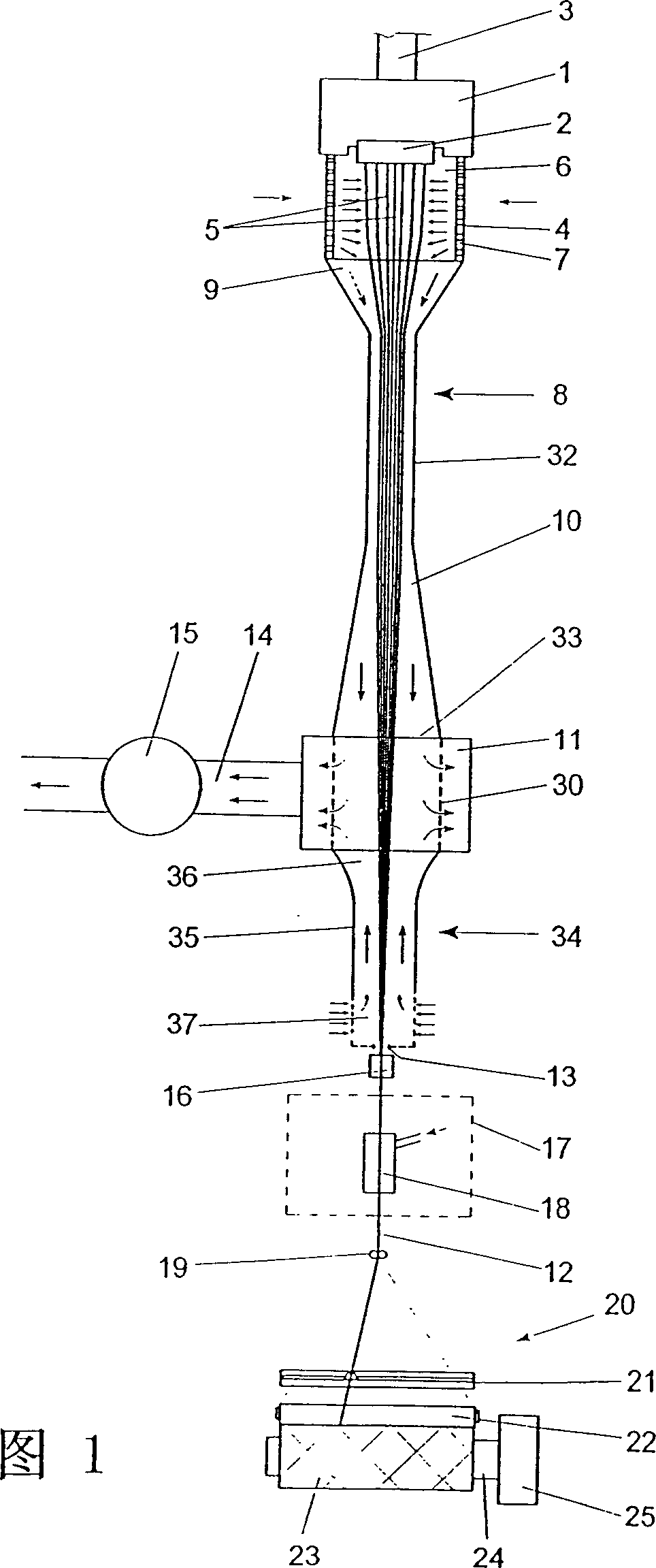
[0030] FIG. 1 shows a first embodiment of a spinning device according to the invention for spinning synthetic filaments.

[0031]Filament 12 is spun from a thermoplastic material. For this purpose the thermoplastic material is melted in an extruder or pump. The melt is fed to the spinning head 1 via the melt line 3 by means of a spinning pump. A spinneret 2 is mounted on the bottom surface of the spinneret 1 . The melt emerges from the spinneret 2 in the form of filament strands 5 . The monofilaments 5 pass through a spinning shaft 6 as a monofilament bundle, which is formed by a gas inlet tube 4 . To this end, the gas cylinder 4 is arranged immediately below the spinning head 1 and surrounds the monofilaments 5 . A first cooling pipe 8 is connected to the free end of the air inlet tube 4 along the running direction of the filament. The cooling tube has an inlet 9 on the side where the filaments enter. Preferably, the inlet 9 made into a funnel shape is connected with th...


PUM


Abstract

A melt spinning apparatus for spinning a synthetic yarn, wherein the yarn is formed by combining a plurality of filaments and wound to a package by means of a takeup device downstream of the spinning apparatus. Downstream of the spinneret, an inlet cylinder with a gas-permeable wall and a cooling tube are arranged. The cooling tube connects to a suction device such that an air stream forms in the cooling tube in the direction of the advancing yarn. This air stream assists the advance of the filaments and leads to a delayed cooling. To ensure adequate cooling of the filaments within the cooling zone, an air supply device is provided for generating an additional cooling air stream which flows in the axial direction of the cooling tube for cooling the filaments downstream of the inlet to the cooling tube.

Description

technical field [0001] The invention relates to a spinning device for spinning synthetic filaments and to a method for spinning synthetic filaments. Background technique [0002] Such a spinning device and method are known from EP0682720. [0003] In known spinning devices the freshly extruded monofilaments travel in a cooling tube with a negative pressure atmosphere. The cooling tube is placed at a distance from the spinneret such that an air flow for cooling the monofilaments is formed in the cooling tube in the direction of travel of the filaments. The air flow speed and the spinning speed are matched to one another in such a way that the monofilaments are supported by the air flow during their forward movement in the cooling tube. This achieves that the hardening point of the monofilaments is kept away from the spinneret. This consequently delays the crystallization of the polymer, which has a favorable effect on the physical properties of the filament. In this way, ...

Claims


Application Information

Patent Timeline
Patent Type & Authority Patents(China)
IPC IPC(8): D01D5/092
CPCD01D5/092D01D13/00
Inventor 克劳斯·谢弗迪尔特·威莫德特勒弗·舒尔茨汉斯约格·迈塞乌尔里希·恩德斯汉斯-格哈德·胡特彼得·森格罗兰德·尼特施克格哈德·米勒
Owner SAURER GMBH & CO KG
Why Eureka
Try Eureka