
Plant ecological monitoring system based on optical frequency comb

An ecological monitoring and optical frequency comb technology, applied in the optical field, can solve the problems of long measurement time, inability to measure plant morphology and analyze spectral components at the same time, and limited accuracy, so as to meet the requirements of accurate and real-time information acquisition and real-time measurement. , to achieve the effect of integration

Active Publication Date: 2020-09-29
EAST CHINA NORMAL UNIV
View PDF18 Cites 0 Cited by
  • Summary
  • Abstract
  • Description
  • Claims
  • Application Information

AI Technical Summary

Problems solved by technology

[0003] The traditional technical means of measuring plant ecology cannot realize simultaneous measurement of plant morphology and analysis of spectral components, and separate measurement will bring a series of problems such as complex system, asynchronous measurement, and long measurement time
In addition, the point-matrix scanning measurement of lidar is limited by the scanning time of the scanning robot arm, which requires a certain measurement time and cannot achieve real-time restoration analysis
The disadvantage of area array CCD imaging technology is that the sensor array is complex and the accuracy is limited
Traditional spectral analysis instruments usually use spectral separation to measure and restore separately. The disadvantage is that the measurement efficiency is low and the measurement accuracy is limited.

Method used


Image

  • Plant ecological monitoring system based on optical frequency comb
  • Plant ecological monitoring system based on optical frequency comb

Examples


Embodiment

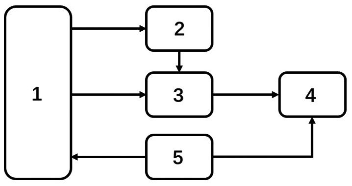
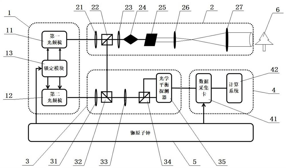
[0021] Example: such as figure 1 , 2 As shown, the present embodiment specifically relates to a plant ecological monitoring system based on an optical frequency comb, which includes an optical frequency comb light source module 1, an optical monitoring module 2, a detector module 3, a data acquisition and processing module 4 and The clock synchronization module 5, the two output ends of the optical frequency comb light source module 1 are respectively connected with the input end of the optical monitoring module 2 and the input end of the detector module 3, and the output end of the optical monitoring module 2 is connected with the input end of the detector module 3 The output end of the detector module 3 is connected with the data acquisition and processing module 4, and the two output ends of the clock synchronization module 5 are respectively connected with the input end of the optical frequency comb light source module 1 and the input end of the data acquisition and proces...


PUM


Abstract

The invention discloses a plant ecological monitoring system based on an optical frequency comb. The system comprises an optical frequency comb light source module, an optical monitoring module, a detector module, a data acquisition and processing module and a clock synchronization module. The optical frequency comb light source module outputs monitoring light and reference light with repetition frequency difference; the monitoring light acts on a monitoring object after the power, wavelength and light beam of the monitoring light are adjusted by the optical monitoring module; the detector module receives monitoring light reflected by a monitoring object, the detector module performs beat frequency on returned monitoring light and reference light, and the data acquisition and processing module acquires a beat frequency signal sent by the detector module, analyzes the beat frequency signal and restores an absorption spectrum and morphological characteristics of the monitoring object inreal time. The plant ecological monitoring system has the advantages that the measuring speed is extremely high, the precision is high, the growth form and the physiological state of the plant can beaccurately reflected in real time, and an enough, timely and accurate information model is provided for relevant instant decisions in the relevant fields of agricultural production, botanical researchand the like.

Description

technical field [0001] The invention belongs to the field of optical technology, and in particular relates to a plant ecological monitoring system based on an optical frequency comb. Background technique [0002] With the growth of plants, their overall morphology (branches, leaves, stems, stems, flowers, fruits) will change slowly. At the same time, affected by the growth environment, such as changes in temperature, climate, and soil nutrients, plant growth The composition of the gas produced during the process changes slightly. High-precision shape measurement of the plant growth process and high-precision analysis of the gas components generated during its environmental interaction are necessary means to accurately monitor the dynamic growth process, physiological changes, and physical signs of plants. At this stage, the means of shape monitoring mainly rely on laser radar dot scan or area array CCD imaging technology, and the analysis of gas composition mainly relies on...

Claims


Application Information

Patent Timeline
Patent Type & Authority Applications(China)
IPC IPC(8): G01B11/24G01N21/39
CPCG01B11/2441G01N21/39
Inventor 朱志伟刘洋李文雪罗大平顾澄琳
Owner EAST CHINA NORMAL UNIV
Learn More