
High-sensitivity ultrasonic detection method based on digital optical frequency comb and microcavity array

An ultrasonic detection and digital light technology, applied in the field of optical signal processing, can solve the problems of high power consumption and large volume, and achieve the effect of fast frequency sweeping, high detection accuracy, and high-precision spectral scanning.

Inactive Publication Date: 2020-09-29
SUN YAT SEN UNIV
View PDF4 Cites 7 Cited by
  • Summary
  • Abstract
  • Description
  • Claims
  • Application Information

AI Technical Summary

Problems solved by technology

In these ultrasonic sensing applications, a single ultrasonic sensing point can no longer meet the application requirements of most occasions, and the array ultrasonic sensing technology helps to improve the detection efficiency in large-scale projects
The traditional array ultrasonic transducer probe is a plurality of different ultrasonic transducers working independently at the same time, converting the ultrasonic signals into electrical signals and then summarizing them to the processing unit for demodulation and analysis. Since each ultrasonic transducer requires power supply and Signal return lines, a large number of ultrasonic transducers bring high power consumption, but also require a more complex wiring system, and the volume is relatively large. Therefore, how to achieve a highly integrated, larger number of ultrasonic arrays and lower Ultrasonic detection of power consumption has become the current difficulty

Method used


Image

  • High-sensitivity ultrasonic detection method based on digital optical frequency comb and microcavity array
  • High-sensitivity ultrasonic detection method based on digital optical frequency comb and microcavity array
  • High-sensitivity ultrasonic detection method based on digital optical frequency comb and microcavity array

Examples


Embodiment Construction

[0026] The accompanying drawings are for illustrative purposes only, and should not be construed as limiting the present invention; in order to better illustrate this embodiment, certain components in the accompanying drawings will be omitted, enlarged or reduced, and do not represent the size of the actual product; for those skilled in the art It is understandable that some well-known structures and descriptions thereof may be omitted in the drawings. The positional relationship described in the drawings is for illustrative purposes only, and should not be construed as limiting the present invention.

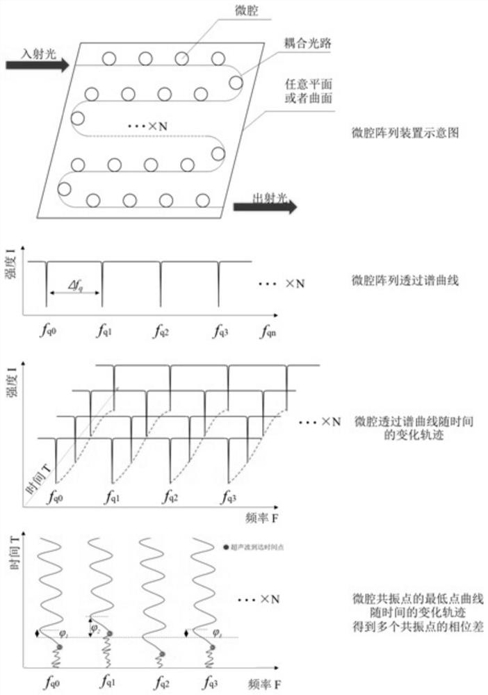
[0027] Such as figure 1 and figure 2 As shown, a highly sensitive ultrasonic detection method based on a digital optical frequency comb and a microcavity array 6, which includes a detection signal transmitting unit, a microcavity array 6 sensing unit, a detection device and a signal demodulation unit; these three components Some of them can be connected in a wired way throug...


PUM


Abstract

The invention belongs to the field of optical signal processing and the field of sensing, and relates to a high-sensitivity ultrasonic detection method based on a digital optical frequency comb and amicrocavity array. An advanced signal processing technology in the field of optical communication is utilized to obtain a digital optical frequency comb signal with a certain bandwidth, and the digital optical frequency comb signal is utilized to scan a micro-cavity photonic device to obtain an ultrafast and high-precision micro-cavity resonance peak scanning spectral line. Meanwhile, only one light path system is required to be coupled with the plurality of micro-cavity structures, so that the equal-interval wavelength distribution of the resonance peaks of the plurality of micro-cavities isrealized. Wavelength positions of resonance peaks of a plurality of micro-cavities are designed; rapid and high-precision detection of the frequency and the power of respective resonance peaks of thelarge number of micro-cavity structures by the digital optical frequency comb can be realized; the efficiency and the processing difficulty of ultrasonic array detection can be remarkably improved; the method can be applied to the fields of ultrasonic array detection, photoacoustic imaging and the like; and meanwhile, a basis is provided for research of an integrated and miniaturized ultrasonic phased array detector.

Description

technical field [0001] The invention belongs to the field of optical signal processing and the field of sensing technology, and more specifically relates to a highly sensitive ultrasonic detection method based on a digital optical frequency comb and a microcavity array. Background technique [0002] Array ultrasonic detection has been widely researched and applied in the fields of national defense security, biomedicine, aerospace, photoacoustic tomography, ultrasonic imaging, interface detection and other industrial engineering fields. In extreme environments (such as imaging of sensitive wounds or dangerous samples, bonding agent inspection, functional ophthalmology imaging) or in complex and restricted environments (such as stray electromagnetic fields, confined spaces, forced dry environments, etc.), non-contact ultrasonic detection appears Particularly important. In these ultrasonic sensing applications, a single ultrasonic sensing point can no longer meet the applicati...

Claims


Application Information

Patent Timeline
IPC IPC(8): G01N29/46
CPCG01N29/46G01N2291/0289
Inventor 张斌潘竞顺李朝晖赵佳鑫
Owner SUN YAT SEN UNIV
Learn More