Optical isolator and laser

An optical isolator and isolation structure technology, applied in the field of optical isolation, can solve the problems of the complex structure of the collimated light output optical isolator, the limited use occasion and scope of the optical isolator, and the large overall size, etc., so as to reduce the material and production costs. , reduce the volume, overcome the effect of high cost

Pending Publication Date: 2020-09-29
光越科技(深圳)有限公司
View PDF6 Cites 2 Cited by
  • Summary
  • Abstract
  • Description
  • Claims
  • Application Information

AI Technical Summary

Problems solved by technology

However, conventional collimated light output optical isolators generally use optical systems such as collimators, beam splitting crystals, optical rotation crystals, negative lenses, and positive lenses to realize collimated light output optical isolators, resulting in a complex structure of collimated light output optical isolators. ,higher cost
At the same time, the overall size is too large, which limits the size of the integrated design of the entire device, which greatly limits the use occasions and scope of the optical isolator.

Method used


Image

  • Optical isolator and laser
  • Optical isolator and laser
  • Optical isolator and laser

Examples


Embodiment 1

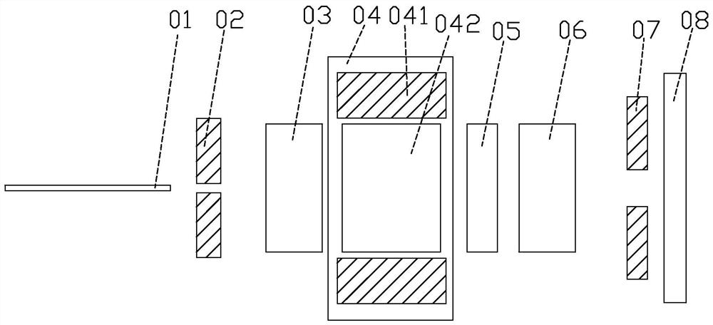
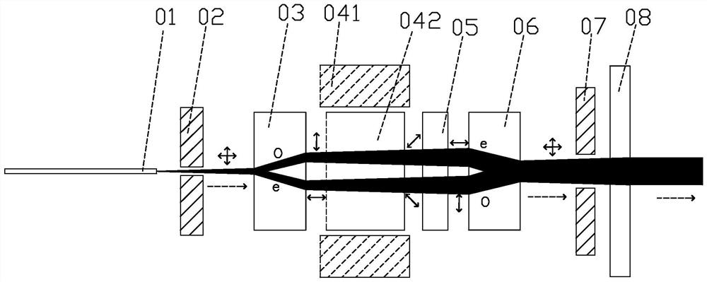
[0025] refer to figure 1 , figure 1 It is a structural schematic diagram of a specific embodiment of an optical isolator in the present invention; the optical isolator includes a divergence angle adjustment module 01 for adjusting the beam divergence angle, a beam isolation structure and a collimating lens 08 arranged along the forward optical path direction, In this embodiment, the beam isolation structure includes a first diaphragm 02, a first dichroic crystal 03, a magneto-optical rotation device 04, a phase rotation crystal 05, a second dichroic crystal 06, and a second diaphragm 07 arranged along the direction of the optical path. Specifically, the magneto-optical rotation device 04 includes a magnetic tube 041 and an optical rotation crystal 042, and the phase rotation crystal 05 can be realized by using a half-wave plate or a quartz optical rotation rod. In addition, in this embodiment, the divergence angle adjustment module 01 is a beam expanding fiber, which expands ...

Embodiment 2

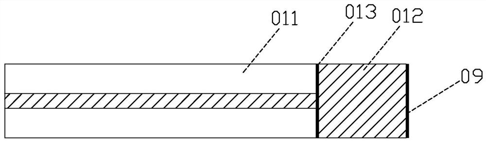
[0030] refer to figure 1 , in this embodiment, when the user uses an optical fiber with a relatively large divergence angle to introduce the beam, the divergence angle adjustment module 01 is realized by using an expanded core fiber, and the expanded core fiber is to reduce the input beam (with a large beam divergence angle). Small divergence angle processing to reduce the divergence angle of the original input beam. refer to Figure 5 , Figure 5 It is a schematic diagram of a specific embodiment of the core-expanded optical fiber of an optical isolator in the present invention. The core-expanded optical fiber 014 is obtained by thermally expanding the core at one end of the optical fiber, and the divergence angle of the optical fiber is reduced by increasing the core diameter of the optical fiber. . Similar to Embodiment 1, an anti-reflection film 09 is coated on the end face of the expanded-core optical fiber 014 as an anti-reflection structure. The optical path structu...

Embodiment 3

[0032] refer to figure 1 , in this embodiment, when the user uses an optical fiber with a relatively large divergence angle to introduce the light beam, the divergence angle adjustment module 01 is realized by using a graded-index fiber. The divergence angle reduction process is performed to reduce the divergence angle of the original input beam. Specifically, refer to Figure 6 , Figure 6 It is a schematic diagram of a specific embodiment of a graded-index optical fiber of an optical isolator in the present invention. In actual use, a section of graded-index optical fiber 015 can be welded at one end of the optical fiber 011. The fusion point is as follows Figure 6 013 in. The divergence angle of the beam can be changed by controlling the length of the graded-index fiber 015. For the specific structure of the graded-index fiber 015, see Figure 7 , including cladding 0151 and core 0152, graded index fiber is also called self-focusing fiber, refer to Figure 8 , Figur...


PUM


Abstract

The invention discloses an optical isolator and a laser. According to the optical isolator, a divergence angle adjusting module used for adjusting a divergence angle of a light beam, a light beam isolation structure and a collimating lens are arranged in a light path direction so as to Implement collimated light output, optical elements needed by the collimated light output optical isolator are effectively reduced, a material and manufacturing cost of the optical isolator is reduced, a size of the optical isolator is decreased, popularization of the collimated light output optical isolator isfacilitated, and technical problems that in the prior art, an optical isolator is complex in structure, high in cost and large in size, and a use occasion is limited are solved.

Description

technical field [0001] The invention relates to the field of optical isolation, in particular to an optical isolator and a laser. Background technique [0002] In a high-power pulsed laser system, in order to prevent the back-reflected laser from entering the laser system and damaging the internal components of the laser when the laser is processing the end surface of the material, it is necessary to add an optical isolator at the output end of the laser so that the light can only pass through in one direction. , to isolate backreflected light. Especially for laser marking or laser cleaning, a collimated light output optical isolator is generally used. However, conventional collimated light output optical isolators generally use optical systems such as collimators, beam splitting crystals, optical rotation crystals, negative lenses, and positive lenses to realize collimated light output optical isolators, resulting in a complex structure of collimated light output optical i...

Claims


Application Information

Patent Timeline
Patent Type & Authority Applications(China)
IPC IPC(8): G02F1/09G02F1/00
CPCG02F1/093G02F1/09G02F1/0081
Inventor 胡江民龙跃金郜军红张峰
Owner 光越科技(深圳)有限公司
Why Eureka
Try Eureka