

TC-SAW device and manufacturing method thereof
A TC-SAW, manufacturing method technology, applied in electrical components, impedance networks, etc., can solve the problems of insufficiency, frequency drift, overall performance deterioration, etc., to achieve the effect of frequency stability, high Q value, and easy peeling
Pending Publication Date: 2020-09-29
SHENZHEN MICROGATE TECH
View PDF0 Cites 3 Cited by
- Summary
- Abstract
- Description
- Claims
- Application Information
AI Technical Summary
Problems solved by technology
For duplexer frequency bands (such as Band2, 3, 8, 25, 26) with very narrow frequency intervals between the transmitting end and the receiving end, the frequency drifts and the overall performance deteriorates under long-term load power operation, which cannot meet the needs of modern mobile communications. needs
Method used
View moreImage
Smart ImageViewing Examples

Examples
Embodiment
[0085] Such as Figure 10 Shown is a measured temperature coefficient diagram of a TC-SAW device. It can be seen from the figure that its temperature coefficient is -15.8 ppm / K.
Login to View More PUM
| Property | Measurement | Unit |
|---|---|---|
| Temperature coefficient | aaaaa | aaaaa |
| Thickness | aaaaa | aaaaa |
Abstract
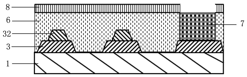
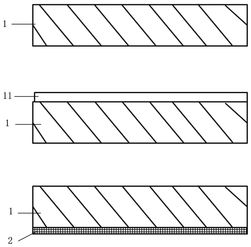
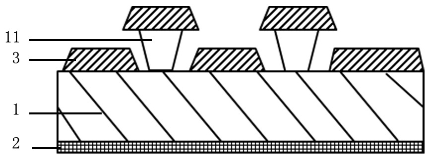
The invention relates to the field of surface acoustic wave devices. A conventional STD-SAW device is very sensitive to temperature change, and performance change is relatively obvious. Therefore, theinvention provides a TC-SAW device, which comprises a piezoelectric material substrate, an interdigital electrode arranged on the piezoelectric material substrate, a temperature compensation layer covering the interdigital electrode, a third metal PAD layer on the piezoelectric material substrate and a passivation layer on the outermost layer. A manufacturing method comprises the following steps:coating a photoresist layer, depositing a metal film, depositing a first layer of interdigital electrode layer, depositing a second layer of electrode, depositing a temperature compensation material,and depositing a passivation layer for isolating air and the like. The temperature coefficient of the TC-SAW device can reach 0 ppm / K to-25 ppm / K, frequency stability is improved, the Q value is improved, and high requirement of mobile communication equipment can be met; the manufacturing method can be used for manufacturing resonators, filters, duplexers and other elements and is wide in application.
Description
technical field [0001] The invention relates to a surface acoustic wave device chip, in particular to a TC-SAW device and a manufacturing method thereof. Background technique [0002] With the rapid development of mobile communication technology, it has developed from the initial 2G to 3G, and then to today's 4G. It is believed that we will enter the 5G era in the near future. Handheld terminal devices have more and more functions and more and more frequency bands. Such as: GSM, TD_SCDMA, WCDMA, TDD_LTE, FDD_LTE and GPS, Bluetooth, WiFi and other different functions combined in one product. This also poses challenges to design and mass production. Frequency resources are becoming more and more crowded, and the guard interval between frequency bands of different communication systems is getting smaller and smaller. On the one hand, this puts stricter requirements on the frequency spectrum and power of the transmitting end of each system, ensuring that the transmitted signal...
Claims
Login to View More Application Information
Patent Timeline
 IPC IPC(8): H03H9/02H03H9/145
CPCH03H9/02543H03H9/02622H03H9/02834H03H9/02984H03H9/14502H03H9/14541H03H9/145H03H9/02
Inventor 宋崇希姚艳龙
Owner SHENZHEN MICROGATE TECH