

Multi-mandrel machining center with micro-motion compensation function
A machining center and spindle machining technology, applied in the direction of manufacturing tools, comprehensive factory control, and other manufacturing equipment/tools, can solve the problems of limited internal space of machining centers, increased structural complexity, workpiece machining deviation, etc., to facilitate production operations and equipment management, improve the overall operating efficiency, and reduce the operating space
- Summary
- Abstract
- Description
- Claims
- Application Information
AI Technical Summary
Problems solved by technology
Method used
Image

Examples
Embodiment 1
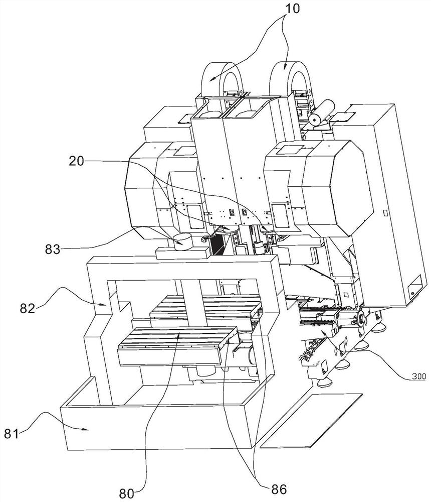
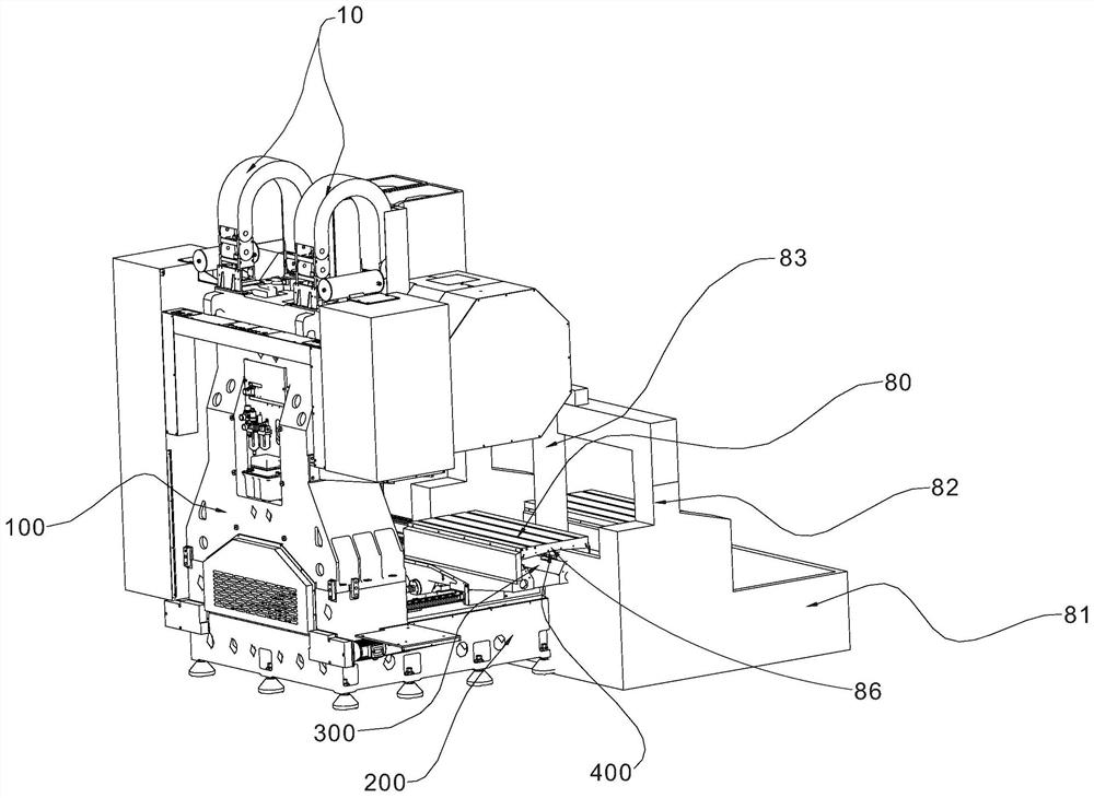
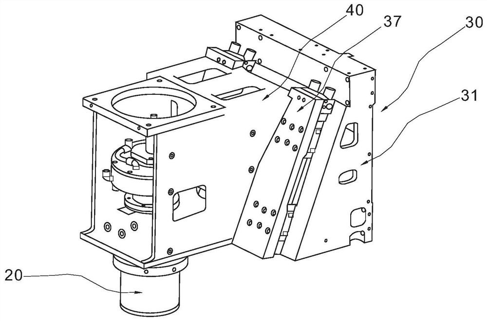
[0025] Such as Figure 1 to Figure 6As shown, a multi-spindle machining center with micro-motion compensation function includes a main base 200, a main column 100, a saddle 300, a worktable 400, two spindle processing units, and a workpiece pallet exchange mechanism. The main column 100 is fixed on the main base 200 and is perpendicular to the ground, the spindle processing unit is slidably connected to the main column 100, the saddle 300 is slidably connected to the main base 200, and a Y-axis driving mechanism is connected between the saddle 300 and the main base 200 , the workbench 400 is slidably connected to the saddle 300, and an X-axis driving mechanism is connected between the workbench 400 and the saddle 300. The spindle processing unit includes a spindle 20 , a micro-motion compensation mechanism 30 and a unit body 40 , the spindle 20 is mounted on the unit body 40 , and a Z-axis driving device 10 is provided between the spindle processing unit and the column 100 . ...
Embodiment 2
[0028] There are three spindle processing units. All the other are with embodiment 1.
Embodiment 3
[0030] There are four spindle processing units. All the other are with embodiment 1.
PUM
 Abstract
Description
Claims
Application Information