Sensor packaging structure and packaging method

A technology of packaging structure and packaging method, which is applied in the field of semiconductors, and can solve problems such as punching and bending of bonding wires, mold blocking by colloid, and high packaging costs

Active Publication Date: 2020-10-02
FOREHOPE ELECTRONICS NINGBO CO LTD
View PDF5 Cites 2 Cited by
  • Summary
  • Abstract
  • Description
  • Claims
  • Application Information

AI Technical Summary

Problems solved by technology

[0004] However, in the current sensor packaging structure, when the plastic package is made for packaging, due to the high injection pressure and mold clamping pressure, it is easy to have defects such as overflow of glue, arc bending of the binding line, and glue blocking the mold, resulting in sensor The yield of the package structure is low
Moreover, the production of plastic packaging requires the use of injection molding machines and molds corresponding to different structures, so the current packaging cost is relatively high

Method used


Image

  • Sensor packaging structure and packaging method
  • Sensor packaging structure and packaging method
  • Sensor packaging structure and packaging method

Examples


Embodiment Construction

[0034] In order to make the purpose, technical solutions and advantages of the embodiments of the present invention clearer, the technical solutions in the embodiments of the present invention will be clearly and completely described below in conjunction with the drawings in the embodiments of the present invention. Obviously, the described embodiments It is a part of embodiments of the present invention, but not all embodiments. The components of the embodiments of the invention generally described and illustrated in the figures herein may be arranged and designed in a variety of different configurations.

[0035] Accordingly, the following detailed description of the embodiments of the invention provided in the accompanying drawings is not intended to limit the scope of the claimed invention, but merely represents selected embodiments of the invention. Based on the embodiments of the present invention, all other embodiments obtained by persons of ordinary skill in the art wi...


PUM

PropertyMeasurementUnit
transmittivityaaaaaaaaaa

Abstract

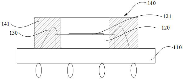
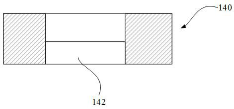
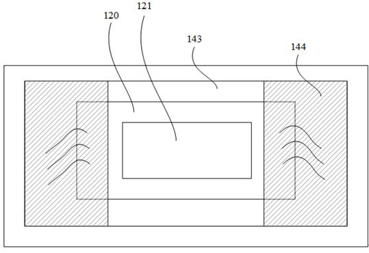
The invention provides a sensor packaging structure and a packaging method, and belongs to the technical field of semiconductors. The sensor packaging structure comprises: a substrate, wherein a sensing chip is arranged on the surface of the substrate, the working area of the sensing chip faces one side far away from the substrate, the circuit of the sensing chip is connected with the circuit of the substrate through a binding wire, a first accommodating groove is formed in the plate surface of a packaging cover plate, the first accommodating groove is filled with an insulating colloid, the packaging cover plate is arranged on the side, provided with the sensing chip, of the substrate in a covering mode, the binding wire is contained in the first accommodating groove so as to be embedded with the insulating colloid, the insulating colloid is used for bonding the packaging cover plate to the substrate, a second accommodating groove is formed in the side, close to the sensing chip, of the packaging cover plate, and the sensing chip is contained in the second accommodating groove. The invention aims to provide the sensor packaging structure and the packaging method, so that the binding wire connected between the sensing chip and the substrate can be well arranged and protected, the yield of the packaging structure is improved, and the packaging cost is reduced.

Description

technical field [0001] The invention relates to the technical field of semiconductors, in particular to a sensor packaging structure and packaging method. Background technique [0002] With the iteration of the semiconductor industry, the types and structures of sensor sensing chips are constantly being updated, and sensing chips such as charge coupled devices (CCD: charge couple device), CMOS chips, and contact image sensors (CIS: contact image sensor) have been developed. Generally, in practical applications, the sensing chip needs to be packaged to form a sensor device for use. [0003] The current sensor packaging structure includes a substrate, a sensor chip, a light-transmitting glass, and a plastic package, wherein the sensor chip is mounted on the substrate and bound by a bonding wire, and the light-transmitting glass is bonded to the working area of ​​the sensor chip by colloid ( For example, the photosensitive area of ​​the photosensitive chip), the sensing chip, ...

Claims


Application Information

Patent Timeline
Patent Type & Authority Applications(China)
IPC IPC(8): H01L27/146H01L27/148
CPCH01L27/14618H01L27/14634H01L27/14636H01L27/1469H01L27/14806
Inventor 钟磊何正鸿
Owner FOREHOPE ELECTRONICS NINGBO CO LTD
Why Eureka
Try Eureka