Brake device of steel bar friction welding machine

A technology of friction welding and braking device, applied in the field of braking device, can solve the problems of high welding frequency, influence of workpiece welding quality, reducing welding production and processing quality, etc., so as to improve welding production and processing quality, ensure the effect of emergency stop, and ensure work. economic effect

Inactive Publication Date: 2020-10-09
徐舒婕
View PDF0 Cites 1 Cited by
  • Summary
  • Abstract
  • Description
  • Claims
  • Application Information

AI Technical Summary

Problems solved by technology

[0003] At present, most of the known fast braking methods for the main shaft of friction welding machines are independent mechanical braking methods; specifically, a clutch and a brake are set between the main shaft and the power drive (electrical or hydraulic motor), , the power is transmitted to the main shaft through the clutch, which drives the main shaft to rotate; when the main shaft needs to brake quickly, the clutch is disconnected, and the brake presses the brake pads under the action of the brake cylinder, and the friction between the brake pads forces the main shaft to stop quickly. down to achieve the purpose of fast braking; in order to reduce the heat generation of clutches and brakes and prolong their life, wet friction plates are generally used; this braking method, because of the high frequency of welding, the brake pads wear quickly, and need to be replaced frequently, and the replacement It is very cumbersome and labor-intensive, and it is easy to damage the main shaft. With the wear of the brake pads, it will become slow to perform emergency stop work. Moreover, when the motor reaches zero speed, the drive will easily overshoot the motor speed and torque. Oscillating from zero speed to negative speed makes the rotating shaft swing slightly back and forth during the brake stop process, which further affects the welding quality of the workpiece, reduces the quality of welding production and processing, and affects the economic benefits of the work. Therefore, the present invention proposes a The brake device of the steel bar friction welding machine is used to solve the above problems

Method used


Image

  • Brake device of steel bar friction welding machine
  • Brake device of steel bar friction welding machine
  • Brake device of steel bar friction welding machine

Examples


Embodiment Construction

[0026] The technical solutions in the embodiments of the present invention will be clearly and completely described below. The embodiments of the present invention and all other embodiments obtained by persons of ordinary skill in the art without making creative efforts belong to the protection scope of the present invention.

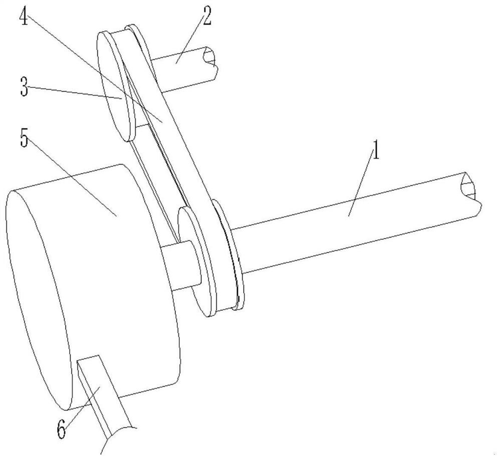
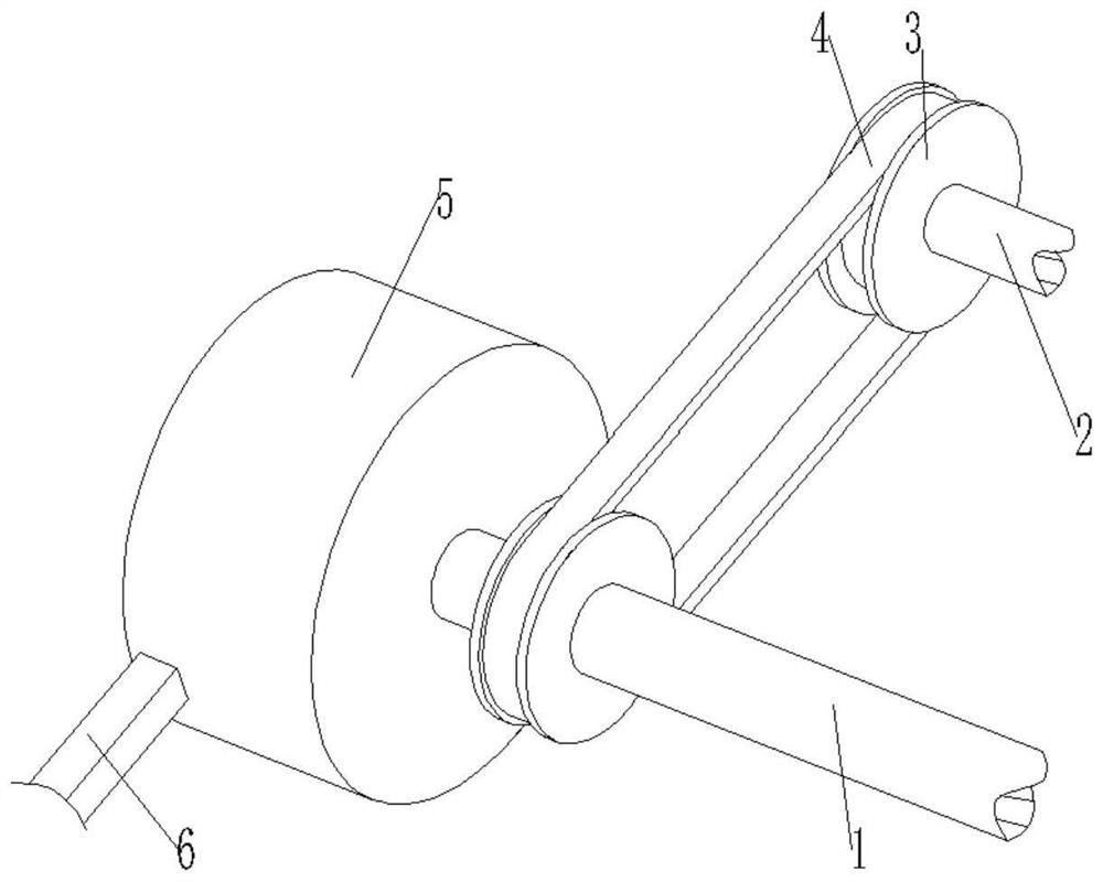
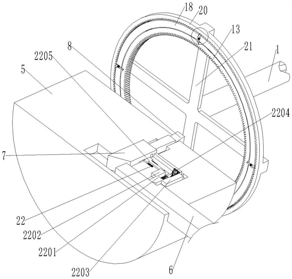
[0027] see figure see Figure 1 to Figure 6 , the present invention provides a technical solution: a brake device for a steel bar friction welding machine, including a rotating main shaft 1, a transmission shaft 2, a pulley 3, a transmission belt 4, a placing round body 5 and an emergency stop auxiliary locking mechanism 22;

[0028] Both the rotating main shaft 1 and the transmission shaft 2 are sleeved with pulleys 3, and the belt pulleys 3 are connected in rotation through a transmission belt 4, and one end of the rotating main shaft 1 is set through and placed in the circular body 5;

[0029] A hydraulic push rod 6 is movable in the placed round bo...


PUM


Abstract

The invention discloses a brake device of a steel bar friction welding machine. A belt wheel and a transmission belt which are arranged on the brake device to drive a rotating main shaft to rotate andoperate, and a second movable clamping block arranged in a fixed ring and a positioning clamping groove formed in a rotating ring are clamped and fixed to clamp and position the rotating ring, and therefore, the rotating main shaft can rapidly operate and suddenly stop, a brake of the rotating main shaft of the friction welding machine does not produce suddenly stop sliding when stopping working,the rotating main shaft is guaranteed to not slightly swing back and forth in the brake stopping process, the workpiece welding quality is guaranteed, and the work economic benefits are guaranteed. The brake device has a clamping effect on the position of a T-shaped movable extrusion block, so that the T-shaped movable extrusion block does not rebound reversely in the moving process, the clampingconnection of the second movable clamping block and the positioning clamping groove is prevented from being loosen, and the sudden stop effect is ensured.

Description

technical field [0001] The invention relates to the technical field of welding equipment, in particular to a brake device for a steel bar friction welding machine. Background technique [0002] Friction welding machine refers to the equipment that generates heat energy during rotation, and then applies appropriate pressure to complete welding; according to different energy input methods, friction welding machine is divided into two types: continuous drive type and inertia type; the former consists of fixtures, transmission mechanisms, and pressure mechanisms. , brake device and control device; the latter is composed of fixture, transmission mechanism, flywheel, pressurization mechanism and control device; friction welding machine: use the heat generated by the friction between the end faces of the workpiece to make it reach a plastic state, and then top forging is completed Welding method; because the chips are often firmly stuck to the cutter head when turning the workpiece...

Claims


Application Information

Patent Timeline
Patent Type & Authority Applications(China)
IPC IPC(8): B23K20/12B23K20/26
CPCB23K20/12B23K20/26
Inventor 徐舒婕
Owner 徐舒婕
Why Eureka
Try Eureka