Fiber reinforced composite structure comprising stitch-member and the method for producing the same

A technology of reinforced composites and manufacturing methods, applied in the direction of fiber chemical characteristics, chemical instruments and methods, vehicle parts, etc., can solve problems such as low thermal conductivity

Pending Publication Date: 2020-10-09
KOREA INST OF SCI & TECH
View PDF6 Cites 3 Cited by
  • Summary
  • Abstract
  • Description
  • Claims
  • Application Information

AI Technical Summary

Problems solved by technology

[0014] As mentioned above, embodiments of the present invention intend to solve the problem of low thermal conductivity along the thickness direction of unidirectional (unidirectional), biaxial (biaxial) composite laminates and the like.
[0015] In addition, embodiments of the present invention intend to solve the problem that existing composite materials only selectively have tensile strength and thermal conductivity in a high-heating, high-temperature environment

Method used


Image

  • Fiber reinforced composite structure comprising stitch-member and the method for producing the same
  • Fiber reinforced composite structure comprising stitch-member and the method for producing the same
  • Fiber reinforced composite structure comprising stitch-member and the method for producing the same

Examples


Embodiment 1

[0090] Example 1: Fiber-reinforced composite structure (primary suture, PAN system)

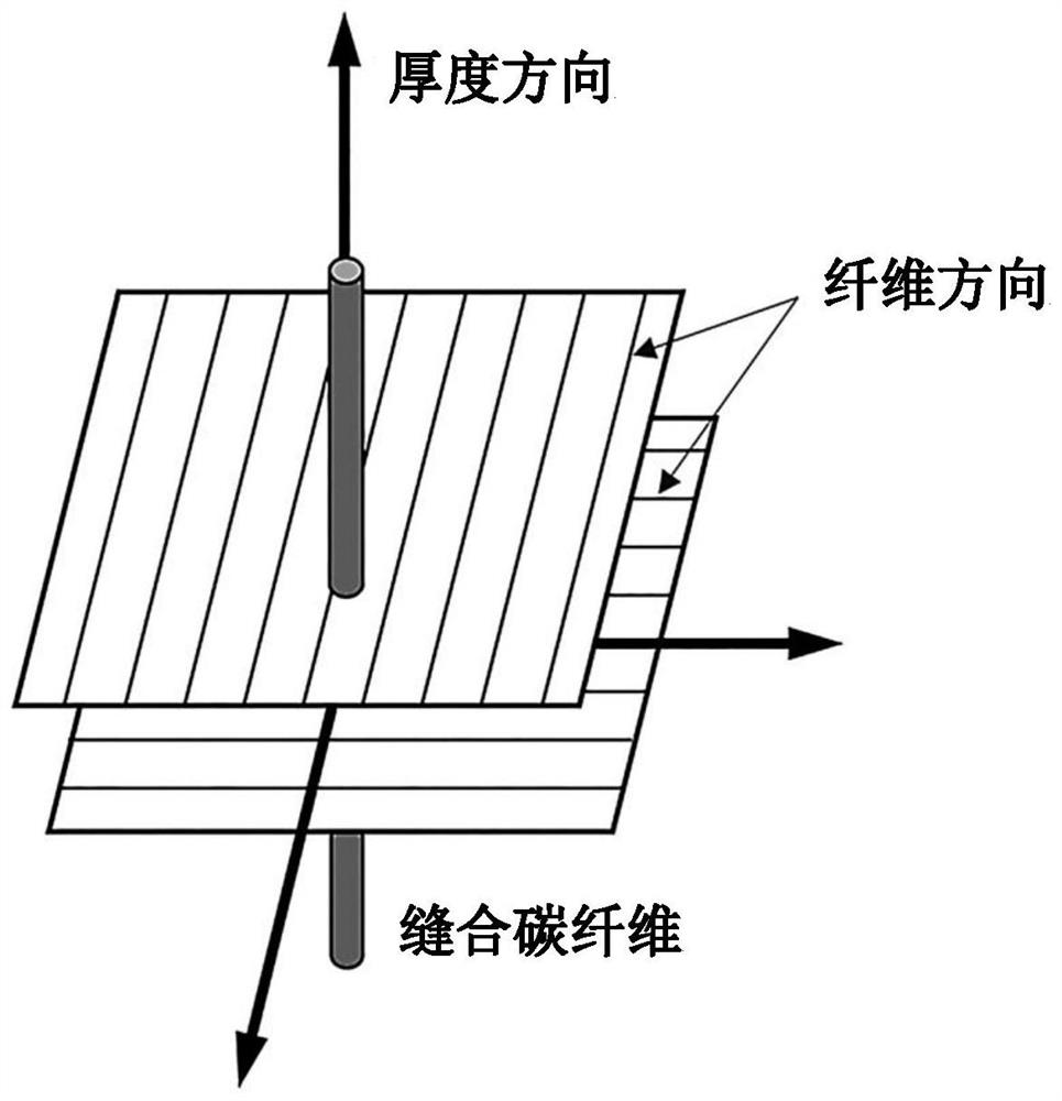
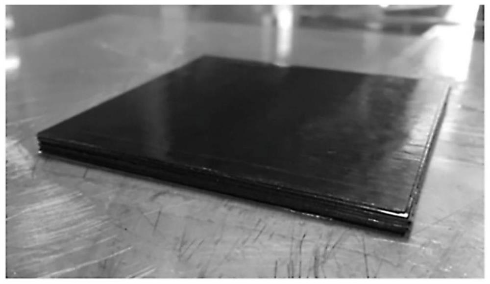
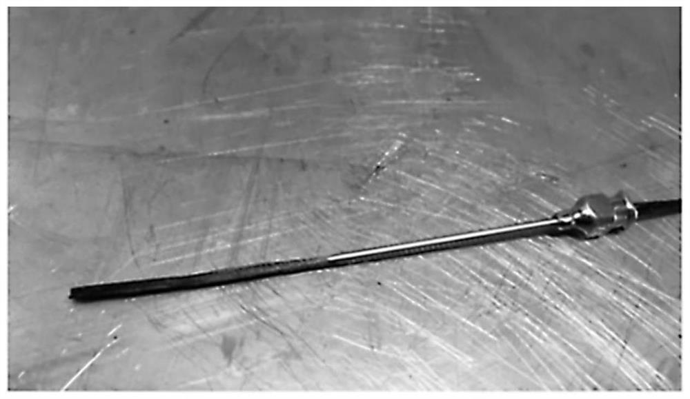
[0091] A prepreg containing PAN-based carbon fibers (USN200A, SK Company) was cut into a regular quadrilateral shape of 8 cm in width and length along directions perpendicular to and parallel to the direction of the fibers. For this prepreg sheet, odd-numbered layers were rotated by 0°, and even-numbered layers were rotated by 90° so that the directions of fibers of adjacent layers were perpendicular to each other, and 22 layers were stacked to manufacture a fiber-reinforced structure. Then, a PAN-based carbon fiber (T700, TORAY Co., Ltd.) was passed through a suture needle of a predetermined thickness, and this was used to suture one point inside a circle with a diameter of 19 mm in the fiber-reinforced structure. After the penetrating needle point is fully raised upwards, the fiber is pulled out so that the fiber becomes a pattern of penetrating the prepreg ( Figure 2c , 2d ). After the...

Embodiment 2

[0092] Example 2: Fiber-reinforced composite structure (primary stitching, asphalt system)

[0093] A fiber-reinforced composite structure was produced in the same manner as in Example 1 except that pitch-based carbon fibers (XN-90-60S, NGF) were used as carbon fibers to be stitched through the fiber-reinforced structure.

Embodiment 3

[0094] Example 3: Fiber-reinforced composite structure (4 sutures, PAN system)

[0095] A fiber-reinforced composite structure was produced in the same manner as in Example 1, except that four points inside a circle with a diameter of 19 mm in the fiber-reinforced structure were sewn.


PUM

PropertyMeasurementUnit
elastic modulusaaaaaaaaaa
tensile strengthaaaaaaaaaa

Abstract

The present specification provides a carbon fiber reinforced composite structure comprising: a plurality of carbon fiber reinforced sheets, which are laminated; and a stitch member penetrating one ormore carbon fiber reinforced sheets, in which the carbon fiber reinforced sheet includes a plurality of reinforcing carbon fibers arranged in one direction. The carbon fiber reinforced composite structure shows excellent thermal conductivity in a thickness direction.

Description

technical field [0001] The present invention relates to a fiber composite structure and a method for producing the same, and more specifically, to a fiber-reinforced composite structure having excellent mechanical strength and improved thermal conductivity along the stacking direction. [0002] Description of state support for research and development [0003] This study was conducted under the supervision of Kolon Plastic Co., Ltd. with the approval of the Ministry of Industry, Trade and Energy of the Republic of Korea (research project name: aircraft reinforcement panels using PPS, PEEK and carbon fiber UD tapes with a fiber content of 60 wt% or more and "C", "Z" channel development, subject number: 1415158981) support and implementation. [0004] In addition, this research is under the supervision of the Korea Institute of Science and Technology and supported by the Ministry of Science, Technology, Information and Communication of the Republic of Korea (research project na...

Claims


Application Information

Patent Timeline
Patent Type & Authority Applications(China)
IPC IPC(8): B32B9/00B32B9/04B32B5/12B32B5/06B32B38/00
CPCB32B5/12B32B5/06B32B5/26B32B38/00B32B2038/008B32B2260/021B32B2262/106B32B2307/302B32B2605/18B32B2605/08B29C70/222B29C70/54B29C70/48B29C70/32B29K2105/0881B29K2307/04B32B5/024B32B2250/02B32B2260/023B32B2262/0246B32B2307/54B32B2307/542B32B2307/30B32B2307/51B32B3/266B32B2250/20B32B2250/05B32B2307/546B32B5/022B32B2260/046B32B2262/101B32B2262/062B29C70/08B29C70/18B29C70/30D01F9/22D01F9/145B29K2313/00B29K2105/06B32B7/09
Inventor 俞在相洪贤基裴廓镇郑哈娜崔会吉吴侑娜李东原杨澈玟李旼昱金珉局罗元振刘南浩
Owner KOREA INST OF SCI & TECH
Why Eureka
Try Eureka