
Natural gas purification system and method

A purification system and natural gas technology, applied in the field of natural gas, can solve problems such as lack of theory, and achieve the effects of real-time adjustment of parameters, increase of production rate, and optimization of parameters

Pending Publication Date: 2020-10-09
XIAN CHANGQING TECH ENG +1
View PDF0 Cites 1 Cited by
  • Summary
  • Abstract
  • Description
  • Claims
  • Application Information

AI Technical Summary

Problems solved by technology

Since there is no research on the removal process of small devices in China at present, there is a lack of theory as a supporting basis

Method used


Image

  • Natural gas purification system and method
  • Natural gas purification system and method
  • Natural gas purification system and method

Examples


Embodiment 1

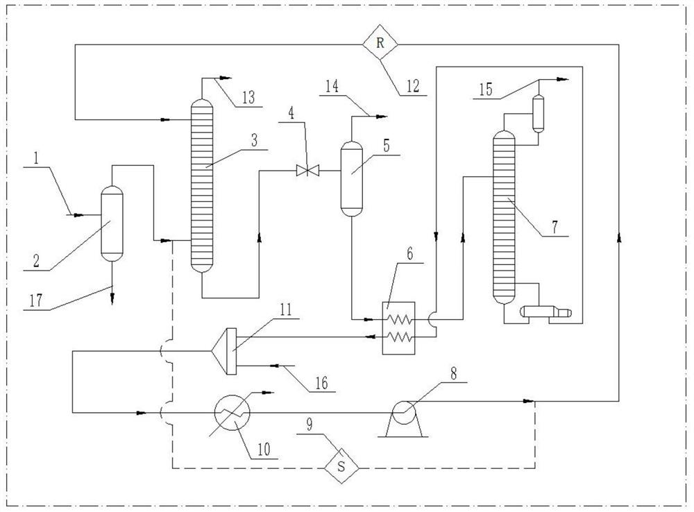
[0035] refer to figure 1 , is a structural schematic diagram of Embodiment 1 of the present invention, a natural gas purification system, comprising

[0036] Intake pipeline 1, one end of the intake pipeline 1 communicates with natural gas raw material gas;

[0037] The gas-liquid separator 2, the air inlet of the gas-liquid separator 2 communicates with the other end of the intake pipeline 1, and the sewage outlet of the gas-liquid separator 2 communicates with the sewage system through the sewage pipeline 17;

[0038] Absorption tower 3, the air inlet of absorption tower 3 is communicated with the outlet of gas-liquid separator 2 by pipeline, and the outlet of absorption tower 3 is communicated with downstream pipeline by absorption tower outlet pipeline 13;

[0039] A regeneration unit, the inlet of the regeneration unit is communicated with the drain of the absorption tower 3 through a pipeline, the gas outlet of the regeneration unit is communicated with the recovery sys...

Embodiment 2

[0045] Compared with Embodiment 1, the difference of this embodiment is that a regulator 9 is connected between the pipeline connected to the inlet of the absorption tower 3 and the pipeline connected to the outlet of the solution pump 8 .

[0046] In actual use: adjust the pressure at the inlet of the absorption tower 3 and the outlet of the solution pump 8 through the regulator 9 to ensure the stability of the inlet pressure of the absorption tower 3 .

Embodiment 3

[0048] Compared with Embodiment 1, the difference of this embodiment is that a circulator 12 is also connected to the pipeline connecting the outlet of the solution pump 8 with the absorption tower 3 .

[0049] In actual use: through the cooperation of the circulator 12 and the solution pump 8, the liquid-phase circulating solution generated by the regeneration unit is pumped into the absorption tower 3 for absorbing H 2 S and CO 2 .


PUM


Abstract

The invention relates to the technical field of natural gas, particularly to a natural gas purification system and method. Natural gas enters a gas-liquid separator through a gas inlet pipeline to besubjected to gas-liquid separation, then, the separated gas phase enters an absorption tower to remove H2S and CO2, a gas phase from which H2S and CO2 are removed is communicated with a downstream pipeline through a pipeline, a liquid phase in the absorption tower enters a regeneration unit for treatment through a pipeline, the treated liquid phase enters a mixer to be mixed with water in a waterinlet pipeline, the mixed liquid phase is cooled through a cooler and then enters an absorption tower through a solution pump to be reused for absorption of H2S and CO2. The natural gas purification system and method provided by the invention can be widely applied to recovery and utilization of domestic remote well site gas, vent gas and site associated gas, have certain economic benefits, can reduce H2S and CO2 emission, have social benefits, and also have reference values in design like real-time parameter adjustment, parameter optimization, yield improvement and energy consumption reduction.

Description

technical field [0001] The invention relates to the technical field of natural gas, in particular to a natural gas purification system and method. Background technique [0002] Natural gas in Xiagu Gas Field of Changqing Oilfield generally contains H 2 S and CO 2 Such acidic medium not only affects the calorific value of natural gas, but also causes serious corrosion to pipelines and containers, seriously affecting the pipeline transportation and utilization of natural gas. Hydrogen sulfide is an active corrosive agent, and its corrosion effect will be more severe in the presence of high pressure, high temperature and liquid water. Carbon dioxide is an acidic component in natural gas. When liquid water exists, the carbonic acid produced is also corrosive to equipment and pipelines. In addition, carbon dioxide is also a non-flammable component in natural gas, which affects the calorific value of natural gas. [0003] Some natural gas well sites in China are unable to keep...

Claims


Application Information

Patent Timeline
IPC IPC(8): C10L3/10B01D53/26B01D53/18B01D53/14
CPCB01D53/1468B01D53/1475B01D53/18B01D53/26C10L3/10C10L3/101C10L3/103C10L3/104Y02C20/40
Inventor 王勇杨光豆锋张新友廖烜华李国明张玉玺王浩郑静张会平
Owner XIAN CHANGQING TECH ENG
Learn More