Construction joint waterproof construction method for combined design of water stop steel plate and anti-crack steel bars

A water-stop steel plate and construction method technology, applied in water conservancy projects, artificial islands, underwater structures, etc., can solve problems such as difficult maintenance, difficult repair, rubber water-stop damage, etc., to reduce maintenance costs in the later period, The effect of reducing the maintenance probability and increasing the flow path of water

Inactive Publication Date: 2020-10-09
CHINA MCC5 GROUP CORP
View PDF8 Cites 5 Cited by
  • Summary
  • Abstract
  • Description
  • Claims
  • Application Information

AI Technical Summary

Problems solved by technology

However, the practice of rubber waterstops is often difficult to obtain better product protection during the construction process, resulting in damage to the rubber waterstop
After the underground structure is formed, it will basically be in a state of water leakage, which is extremely difficult to repair and maintain, which has caused great problems for the use of the underground structure
It is difficult to achieve a good water-stop effect if the water-stop steel plate is used alone. The design of the post-casting belt in the basement often adopts the combination of a

Method used


Image

  • Construction joint waterproof construction method for combined design of water stop steel plate and anti-crack steel bars
  • Construction joint waterproof construction method for combined design of water stop steel plate and anti-crack steel bars
  • Construction joint waterproof construction method for combined design of water stop steel plate and anti-crack steel bars

Examples


Embodiment 1

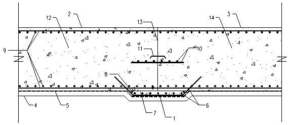
[0052] The construction method of the construction joint waterproof structure of the basement floor waterproof steel plate and the anti-crack steel bar combination design of the embodiment of the present invention:

[0053]The first step is to dig the foundation floor pit to the design elevation and compact it, and then dig 10cm down within the range of 500mm on the left and right sides of the construction joint to form an oblique trench and compact it;

[0054] The second step is to construct a 100mm thick C15 concrete cushion;

[0055] The third step is to lay the pre-laid anti-adhesive waterproof membrane, and lay the membrane according to the shape of the repair within 500mm from the left and right of the construction joint position;

[0056] The fourth step is to bind the Φ8@50 anti-cracking steel mesh in the 10cm deep oblique groove, and leave a steel bar not less than the anchoring length at each of its longitudinal ends to be anchored in the floor;

[0057] The fifth ...

Embodiment 2

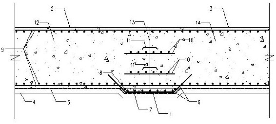
[0065] image 3 It is a schematic diagram of a waterproof structure of a vertical construction joint combined with a basement floor waterproof steel plate and crack-resistant steel bars according to an embodiment of the present invention. The construction method of the combined vertical construction joint of the basement wall "crack-resistant steel bar + water-proof steel plate" of the present invention:

[0066] The first step is to bind the steel bars on the left side of the construction joint;

[0067] The second step is to bind the additional anti-cracking reinforcement Φ8@50 on the outside of the external wall at the construction joint, and extend the anti-cracking reinforcement into the wall reinforcement cage on both sides of the construction joint, and its length is not less than the anchorage length of the anti-cracking reinforcement;

[0068] The third step is to install a 4mm thick steel plate waterstop in the middle of the wall;

[0069] The fourth step is to ins...

Embodiment 3

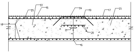
[0076] Figure 4 It is a schematic diagram of the waterproof structure of the combined horizontal construction joint of the basement floor waterproof steel plate and anti-crack steel bar according to the embodiment of the present invention. The construction method of the basement wall "crack-resistant steel bar + water-stop steel plate" combined horizontal construction joint of the present invention:

[0077] The first step is to construct the waterproof layer of the bottom plate;

[0078] The second step is to construct the bottom plate reinforcement, exterior wall reinforcement, outer crack-resistant reinforcement at the construction joints of the outer wall, middle crack-resistant reinforcement, 4mm thick steel plate waterstop, and the lengths of the outer crack-resistant reinforcement and the middle crack-resistant reinforcement to be the same as those on both sides of the construction joint. Meet the anchorage length;

[0079] The third step is to install the template; ...


PUM

PropertyMeasurementUnit
Thicknessaaaaaaaaaa
Thicknessaaaaaaaaaa
Thicknessaaaaaaaaaa

Abstract

The invention relates to a construction joint waterproof construction method for combined design of a water stop steel plate and anti-crack steel bars of basement floors. The construction joint waterproof construction method is characterized by comprising the following steps of a, digging a foundation bottom plate pit to the designed elevation; b, pouring a concrete cushion layer at the bottom ofthe pit; c, laying a pre-laid anti-sticking waterproof coiled material; d, binding an anti-crack steel bar net; e, pouring waterproof concrete in an inclined pit; f, binding the reinforcing steel barson the left side of a construction joint; g, mounting a steel plate waterstop at the position of a concrete bottom plate; h, mounting a formwork at the construction joint; i, pouring waterproof concrete on the left side of the construction joint; j, pouring a concrete cushion layer of the bottom plate on the right side of the construction joint; and k, pouring waterproof concrete on the bottom plate of the right side of the construction part. The construction joint waterproof construction method for combined design of the water stop steel plate and the anti-crack steel bars has the advantagesthat the water stop steel plate and the anti-crack steel bars are combined to form a water stop area, so that the concrete has the anti-crack water stop function, the waterproof effect is good, an additional external anti-crack waterproof layer is arranged at the construction joint of the bottom plate, and the flow path of water is increased.

Description

technical field [0001] The invention relates to a waterproof construction method for construction joints, in particular to a waterproof construction method for construction joints designed in combination with waterproof steel plates and crack-resistant steel bars in a basement. Background technique [0002] For super-long basements or special underground equipment foundations, underground waterproofing is the focus of design and construction. At present, the stamping special structural equipment foundations of the stamping workshops of major automobile manufacturers are basically in a state of water seepage, and in severe cases, it may even affect the production of automobiles. In the design drawings, the design institute often adopts the method of rubber waterstop expansion joints to solve the problem of expansion and deformation of super-long underground structures, so as to theoretically solve the waterproof problem of super-long underground structures. However, the rubb...

Claims


Application Information

Patent Timeline
IPC IPC(8): E02D29/16
CPCE02D29/16
Inventor 孟祥宝卢鹏王莉康前进
Owner CHINA MCC5 GROUP CORP
Why Eureka
Try Eureka