A self-denitration system and process for calciner partitioned organization combustion self-denitration that can adjust the oxygen concentration in the reduction zone

A technology of partition organization and calciner, applied in the field of flue gas denitrification in the cement industry, can solve the problems of limited space in the oxygen-poor combustion zone, small contribution of fuel combustion, and inability to adjust flexibly, achieving strong operability and practicability, and improving Fuel combustion speed, the effect of reducing the cost of environmental protection treatment

Active Publication Date: 2021-04-23
TIANJIN CEMENT IND DESIGN & RES INST
View PDF7 Cites 0 Cited by
  • Summary
  • Abstract
  • Description
  • Claims
  • Application Information

AI Technical Summary

Problems solved by technology

[0011] (1) In the existing linear calciner, the kiln gas enters directly from the bottom of the calciner. Even if the fuel is graded and burned, a reduction zone is formed at the cone of the calciner, which has a certain effect on reducing NOx in the flue gas from the kiln. However, due to The flue gas from the kiln enters the furnace directly, the space of the oxygen-poor combustion zone is limited, the residence time of the denitrification reaction is short, and the denitrification efficiency is generally about 30%.
[0012] (2) The combustion speed of the existing calciner is limited by the temperature of the combustion zone and cannot be burned out quickly. It is necessary to increase the volume of the calciner and prolong the combustion time to meet the demand for burnout. On the one hand, the investment and space occupation are increased, and on the other hand, the The heat dissipation energy consumption of the equipment surface
[0013] (3) The temperature in the combustion zone of the calciner is limited by the crust on the furnace wall, which makes it difficult to further increase the temperature in the combustion zone in the existing technology
When the temperature in the combustion zone is too high, the raw material is prone to liquid phase at high temperature, resulting in skinning problems on the furnace wall
[0014] (4) The combustion temperature of the decomposition furnace is too high and it is easy to burn the refractory material of the furnace wall
[0015] (5) The method of gradient combustion in the existing calciner is limited to the interior of the calciner
Restricted by factors such as the volume of the calciner and the space of the site, the overall denitrification effect needs to be improved
Moreover, the oxygen content of the flue gas in the strong reduction zone in the existing gradient combustion system of the calciner is limited by the fuel combustion in the rotary kiln and cannot be adjusted flexibly; due to the low oxygen concentration, the fuel combustion in the strong reduction zone is limited, making this part of the space difficult Fuel combustion contributes less

Method used


Image

  • A self-denitration system and process for calciner partitioned organization combustion self-denitration that can adjust the oxygen concentration in the reduction zone
  • A self-denitration system and process for calciner partitioned organization combustion self-denitration that can adjust the oxygen concentration in the reduction zone
  • A self-denitration system and process for calciner partitioned organization combustion self-denitration that can adjust the oxygen concentration in the reduction zone

Examples


Embodiment 1

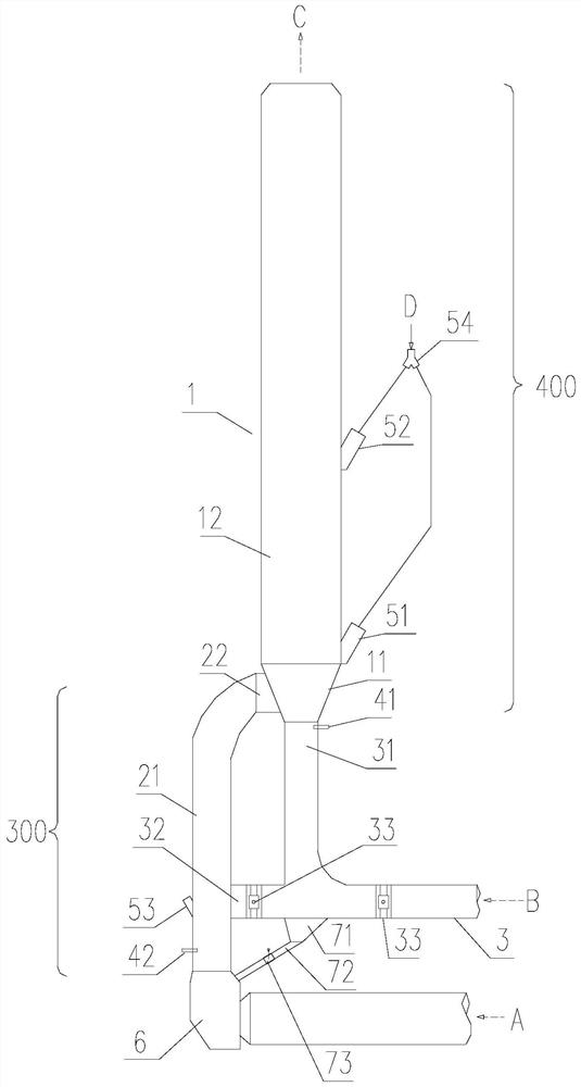
[0060] see Figure 1~4 , the embodiment of the present invention provides a denitrification system for denitrification by combustion in the rich and light oxygen-containing zones of the calciner, including a rotary kiln, a kiln tail smoke chamber 6 connected to the kiln tail of the rotary kiln, a calciner 1, a kiln tail smoke chamber 6 and a decomposition furnace. The kiln gas flue 21 of the furnace 1 and the tertiary air duct 3; the calciner 1, the kiln gas flue 21 and the tertiary air duct 3 are all equipped with refractory materials.

[0061] Rotary kiln flue gas A is the flue gas produced by fuel combustion in the rotary kiln. The temperature is generally 900-1150°C, the oxygen content is generally within 5%, and the NOx concentration in the flue gas is generally 800-1500ppm. The flue gas A of the rotary kiln moves upwards into the kiln gas flue 21 after passing through the kiln tail smoke chamber 6, and enters the calciner cone 11 through the furnace inlet 22 of the kiln ...

Embodiment 2

[0071] The difference from Embodiment 1 is that the calciner cylinder 12 is provided with a narrowing 13 in the middle of the calciner.

[0072] see Figure 5 . Preferably, the calciner column 12 is provided with a calciner middle neck 13 . The shrinkage 13 in the middle of the calciner is located below the upper feeding point 52 of the raw meal of the calciner. The raw meal that enters from the feed point 52 on the raw meal of the calciner moves downward under the action of gravity. By setting the neck 13 in the middle of the calciner, the cross-sectional wind speed at the neck becomes larger than that of the cylinder, which can effectively reduce the raw material. The falling height of the material can be adjusted to prevent material collapse in the calciner.

Embodiment 3

[0074] The difference from Embodiment 1 is that a calciner bottom column section 14 is provided between the calciner cone 11 and the furnace inlet 31 of the tertiary air pipe. The lower feed point 51 of the calciner raw meal and the calciner fuel feed point 41 located below the furnace inlet of the kiln gas flue are located on the column section 14 at the bottom of the calciner.

[0075] see Image 6 . Preferably, a calciner bottom column section 14 is provided between the calciner cone 11 and the furnace inlet 31 of the tertiary air duct. The tertiary air first passes through the column section 14 at the bottom of the calciner, and then enters the cone 11 of the calciner. At this time, the calciner fuel feed point 41 located below the inlet of the kiln gas flue and the lower feed point 51 of the calciner raw material are located on the column section 14 at the bottom of the calciner. The mixture of smoke and gas is more conducive to the ignition of fuel.


PUM


Abstract

The invention discloses a self-denitrification system and process for calcining furnace partitioned organization combustion which can adjust the oxygen concentration in the reduction zone. The side of the furnace is connected, and the tertiary air pipe is connected to the bottom of the calciner cone, forming a horizontally partitioned combustion environment with a central oxygen-rich zone and a peripheral low-oxygen zone on the transverse section of the calciner; the kiln gas flue is a strong reduction zone, and the calciner is a In the embers area, a vertically graded combustion environment with different oxygen peroxide coefficients is formed in the combined combustion space of the kiln gas flue and the calciner; a tertiary air branch pipe is set between the tertiary air duct and the kiln gas flue. The horizontal zoned combustion environment is achieved by the tertiary air entering vertically upward from the bottom center of the calciner, and the flue gas is tangentially rotated into the volute from the side of the calciner to realize the combustion environment; the vertically graded combustion environment is realized by fuel graded feeding. The present invention realizes self-denitrification through zone-organized combustion as a whole, improves self-denitrification efficiency, and improves utilization of space in a strong reduction zone.

Description

technical field [0001] The invention relates to the technical field of flue gas denitrification in the cement industry, in particular to a self-denitration system and process for a calciner with zoned tissue combustion in a calciner that can adjust the oxygen concentration in a reduction zone. Background technique [0002] The calciner is the key equipment in the cement production process. The main component of cement raw meal is calcium carbonate, and the carbonate in cement raw meal is decomposed into oxides in the calciner, which provides a basis for the subsequent clinker sintering reaction in the rotary kiln. Since the decomposition of carbonate needs to absorb a large amount of heat, a certain amount of fuel needs to be fed into the decomposition furnace to supply it. Generally speaking, the fuel in the calciner accounts for about 60% of the fuel consumption in the entire cement clinker calcination process. The combustion status of the fuel in the decomposition direc...

Claims


Application Information

Patent Timeline
Patent Type & Authority Patents(China)
IPC IPC(8): F27D17/00F27D99/00
CPCF27D17/002F27D17/008F27D99/0001
Inventor 陈昌华彭学平胡芝娟陈廷伟林敏燕
Owner TIANJIN CEMENT IND DESIGN & RES INST
Why Eureka
Try Eureka