Annular pumping optical fiber laser amplifier

A technology of pumping optical fiber and pumping light, which is applied to lasers, laser components, phonon exciters, etc., can solve the problems that pumping light power cannot be fully absorbed, increase system manufacturing costs, and increase system heat dissipation requirements. Achieve the effects of suppressing mode instability, reducing the length of the optical path, and reducing the power of pump light

Inactive Publication Date: 2020-10-09
武汉光谷航天三江激光产业技术研究院有限公司
View PDF5 Cites 2 Cited by
  • Summary
  • Abstract
  • Description
  • Claims
  • Application Information

AI Technical Summary

Problems solved by technology

However, since the absorption coefficient of the gain fiber to the pump light is certain, when the length of the gain fiber is too short, a large amount of pump light power cannot be fully absorbed, resulting in energy waste, increasing the heat dissipation requirements of the system, and reducing the efficiency of the laser; and The pump light that cannot be fully absorbed will also increase the index requirements for the cladding optical filter and increase the manufacturing cost of the system

Method used


Image

  • Annular pumping optical fiber laser amplifier
  • Annular pumping optical fiber laser amplifier
  • Annular pumping optical fiber laser amplifier

Examples


Embodiment 1

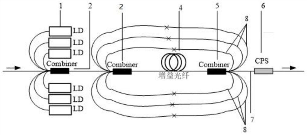
[0030] A ring-pumped fiber laser amplifier utilizes pump light through forward pumping and recycling, and the method of realization is as follows figure 1 As shown, there are three signal pump couplers (Combiner in the figure), specifically two forward signal pump couplers, one reverse signal pump coupler, and the forward signal pump coupler It is relative to the signal light transmission direction. Along the signal light transmission direction, multiple optical fibers enter the signal pump coupler and then one optical fiber is drawn from the signal pump coupler; the reverse signal pump coupler is relatively As far as the signal light transmission direction is concerned, one fiber enters the signal pump coupler along the signal light transmission direction, and then multiple optical fibers are drawn out from the signal pump coupler;

[0031]Including multiple pumping sources (LD in the figure), specifically six in this embodiment, and two forward signal pumping couplers, which...

Embodiment 2

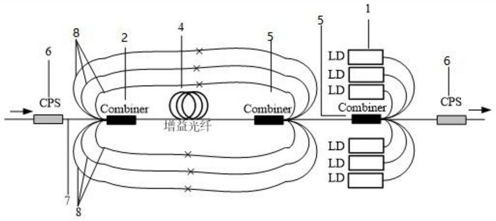
[0034] A ring-pumped fiber laser amplifier uses pump light through reverse pumping, and the method of realization is as follows figure 2 As shown, there are three signal pump couplers, specifically two reverse signal pump couplers and one forward signal pump coupler, and the forward signal pump coupler is relative to the signal light In terms of the transmission direction, along the signal light transmission direction, multiple optical fibers enter the signal pump coupler and then one fiber is drawn from the signal pump coupler; the reverse signal pump coupler is relative to the signal light transmission direction In other words, one optical fiber enters the signal pump coupler along the signal light transmission direction, and then multiple optical fibers are drawn out from the signal pump coupler;

[0035] It includes a plurality of pumping sources, specifically six in this embodiment, and two reverse signal pumping couplers with a (6+1)×1 structure, and its input and outpu...

Embodiment 3

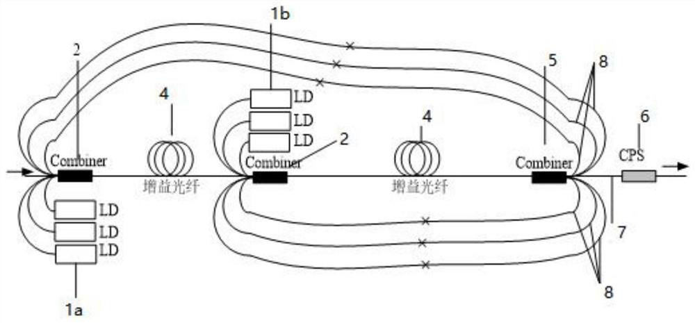
[0038] A ring-pumped fiber laser amplifier, combined with a segmented pump gain fiber and recycled pump light, is implemented as image 3 As shown, there are three signal pumping couplers, specifically two forward signal pumping couplers and one reverse signal pumping coupler. The forward signal pumping coupler is relative to signal light transmission In terms of direction, along the signal light transmission direction, multiple optical fibers enter the signal pump coupler and then one optical fiber is drawn from the signal pump coupler; the reverse signal pump coupler is relative to the signal light transmission direction. In other words, one optical fiber enters the signal pump coupler along the signal light transmission direction, and then multiple optical fibers are drawn out from the signal pump coupler;

[0039] Including a first pump source group and a second pump source group composed of multiple pump sources. In this embodiment, the first pump source group is specific...


PUM

PropertyMeasurementUnit
lengthaaaaaaaaaa
lengthaaaaaaaaaa

Abstract

The invention discloses an annular pumping optical fiber laser amplifier. The annular pumping optical fiber laser amplifier comprises a pumping source, a signal pumping coupler, a gain optical fiber and a pumping filter, the components are fused through optical fibers; the laser is characterized in that the number of the signal pumping couplers is three or more than three; pumping arms between thesignal pumping couplers are connected through optical fiber fusion, and pump light emitted by the pump source enters the gain fiber through the signal pump coupler. Most unabsorbed pump light is output by a pump arm of the other signal pump coupler, the output pump light is injected into the gain optical fiber again through the signal pump coupler to be absorbed in a circulating mode, and the pump light output by the signal fiber of the signal pump coupler is filtered out through the pump filter. According to the fiber laser amplifier scheme, unabsorbed pump light can be cyclically absorbed,the wasted pump light power is reduced, and the slope efficiency of the laser is improved.

Description

technical field [0001] The invention belongs to the technical field of fiber laser amplifiers, in particular to a ring-pumped fiber laser amplifier. Background technique [0002] In high-power fiber laser amplifiers, the power transmitted by the fiber is high, the cross-sectional area of ​​the fiber core is small, and the interaction distance of the transmitted light in the fiber is very long. Non-linear effects such as SBS, SRS, and FWM are easily generated during the laser amplification process. Among them, SBS and SRS are two main factors affecting the output laser power, and their thresholds are inversely proportional to the length of the fiber. In the process of laser development, in order to suppress these nonlinear effects and increase the nonlinear threshold, it is necessary to shorten the gain fiber as much as possible. length. However, since the absorption coefficient of the gain fiber to the pump light is certain, when the length of the gain fiber is too short, a...

Claims


Application Information

Patent Timeline
Patent Type & Authority Applications(China)
IPC IPC(8): H01S3/094H01S3/0941H01S3/102H01S3/067
CPCH01S3/06754H01S3/094084H01S3/0941H01S3/1022
Inventor 雷敏杨雨武春风李强姜永亮吕亮刘厚康宋祥王光斗胡阿健戴玉芬胡金萌
Owner 武汉光谷航天三江激光产业技术研究院有限公司
Why Eureka
Try Eureka