
Broadband low-noise amplifier of improved Darlington structure

A broadband low-noise, amplifier technology, applied in the direction of improving amplifiers to expand bandwidth, amplifiers, improving amplifiers to reduce temperature/power supply voltage changes, etc., can solve the problems of increased amplifier noise, large noise figure, and large changes in amplifier operating current. Achieve the effects of enhancing current stability, resisting current changes, and broadening the bandwidth of amplification gain

Pending Publication Date: 2020-10-09
成都华光瑞芯微电子股份有限公司
View PDF0 Cites 4 Cited by
  • Summary
  • Abstract
  • Description
  • Claims
  • Application Information

AI Technical Summary

Problems solved by technology

In fact, this method makes the working current of the amplifier vulnerable to temperature changes. The resistance value of the resistor network is stable at high and low temperatures, but the turn-on voltage and IV characteristic curve of the amplifier core vary. The voltage cannot follow the voltage required by the amplifier at high and low temperatures, resulting in large changes in the operating current of the amplifier at high and low temperatures
Using the GaAs HBT process to design the LNA chip has a larger noise figure than using the GaAs pHEMT process to design the LNA chip. At the same time, the existence of the current in the feedback path in the Darlington structure adds an additional noise source to the amplifier tube, which greatly increases the noise of the amplifier. Contrary to the need for broadband low noise

Method used


Image

  • Broadband low-noise amplifier of improved Darlington structure
  • Broadband low-noise amplifier of improved Darlington structure

Examples


Embodiment Construction

[0017] The specific embodiments of the present invention are described below so that those skilled in the art can understand the present invention, but it should be clear that the present invention is not limited to the scope of the specific embodiments. For those of ordinary skill in the art, as long as various changes Within the spirit and scope of the present invention defined and determined by the appended claims, these changes are obvious, and all inventions and creations using the concept of the present invention are included in the protection list.

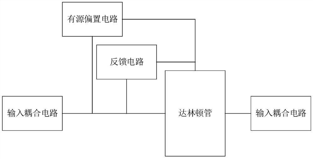
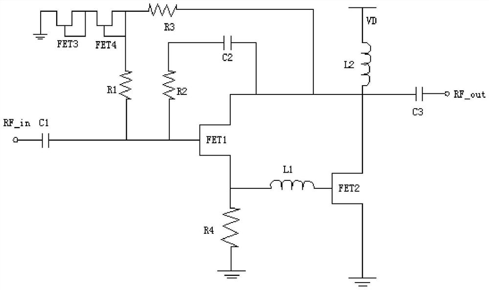
[0018] Such as figure 1 As shown, the embodiment of the present invention discloses an improved Darlington structure broadband low noise amplifier, including a Darlington tube, an active bias circuit, a feedback circuit, an input coupling circuit and an output coupling circuit; the input coupling circuit One end is the amplifier signal input end, and the other end is connected to the grid of the Darlington tube; one end of ...


PUM


Abstract

The invention discloses a broadband low-noise amplifier of an improved Darlington structure. The amplifier comprises a Darlington tube, an active bias circuit, a feedback circuit, an input coupling circuit and an output coupling circuit; one end of the input coupling circuit is an amplifier signal input end, and the other end of the input coupling circuit is connected with the grid of the Darlington transistor; one end of the active bias circuit and one end of the feedback circuit are connected with the grid electrode of the Darlington transistor, and the other end of the active bias circuit and the other end of the feedback circuit are connected with the drain electrode of the Darlington transistor. One end of the output coupling circuit is connected with the drain electrode of the Darlington tube, and the other end is an amplifier signal output end. According to the amplifier, the active bias circuit is adopted to provide voltage for the amplifier tubes, the stability of the bias voltage during temperature change can be ensured, the noise of the amplifier can be effectively reduced by adopting a mode of separating the feedback circuit from the active bias circuit, and meanwhile,the peaking inductor is added between the Darlington tubes to further broaden the amplification gain bandwidth.

Description

technical field [0001] The invention belongs to the technical field of low-noise amplifiers, in particular to an improved Darlington structure broadband low-noise amplifier. Background technique [0002] As the key component of the receiver, the low noise amplifier's performance determines the receiving sensitivity of the receiver to a large extent. In recent years, with the development of ultra-wideband radar and ultra-wideband communication systems, the demand for wideband receivers has increased dramatically, and the demand for wideband low-noise amplifiers has emerged as the times require. The low-noise amplifier using the Darlington structure can meet the wide-band requirements, and the circuit schematic diagram is as follows figure 1 , the design core is mainly the Darlington transistor, the Darlington transistor is also called the composite transistor, which uses a compound connection method to connect the collectors composed of two or more transistors together, and ...

Claims


Application Information

Patent Timeline
IPC IPC(8): H03F1/30H03F1/42
CPCH03F1/301H03F1/42
Inventor 罗孝均李怀明
Owner 成都华光瑞芯微电子股份有限公司
Learn More