Tilting component of tilting rotor unmanned aerial vehicle, tiltable rotor unmanned aerial vehicle and using method

A technology for tilting rotors and drones, applied in the field of drones, can solve problems such as poor tilting efficiency, slow tilting speed, and difficult processing, and achieve the effects of reducing accident rates, improving reliability, and simple processing.

Pending Publication Date: 2020-10-13
XIDIAN UNIV
View PDF1 Cites 1 Cited by
  • Summary
  • Abstract
  • Description
  • Claims
  • Application Information

AI Technical Summary

Problems solved by technology

[0006] Aiming at the defects in the prior art, the purpose of the present invention is to provide a tilting component of a tilting-rotor UAV, a tilting-rotor UAV and a method of use thereof, so as to solve the problem of tilting of the existing tilting-rotor UAV. Poor tilting efficiency, slow tilting speed and difficult processing of rotating parts

Method used


Image

  • Tilting component of tilting rotor unmanned aerial vehicle, tiltable rotor unmanned aerial vehicle and using method
  • Tilting component of tilting rotor unmanned aerial vehicle, tiltable rotor unmanned aerial vehicle and using method
  • Tilting component of tilting rotor unmanned aerial vehicle, tiltable rotor unmanned aerial vehicle and using method

Examples


Embodiment 1

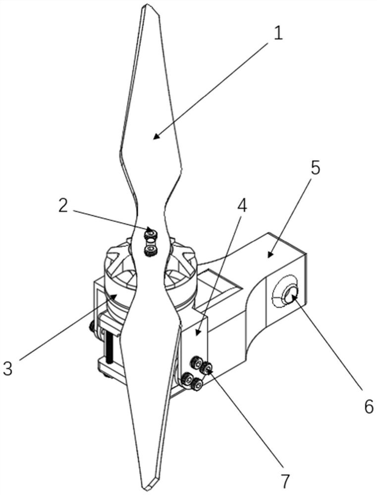
[0042] refer to Figure 1 to Figure 5 As shown, in this embodiment, the tilting components of the tiltrotor UAV include: propeller 1, propeller fixing screw 2, DC brushless motor 3, motor base 4, tilting base 5, and tilting base fixing screw hole 6 , Motor base fixing screw 7, steering gear plate 8, motor fixing screw 9, steering gear fixing screw 10, steering gear 11 and square hollow aluminum tube installation port 12.

[0043] Wherein, the propeller 1 is connected with the DC brushless motor 3, the DC brushless motor 3 is connected with the motor base 4, the motor base 4 is connected with two steering gear discs 8, and the steering gear disc 8 is connected with the steering gear 11 and then the steering gear can be driven Achieving tilting of the propeller.

[0044] Such as Figure 4 and Figure 5 shown, and refer to the Figure 1 to Figure 3 It can be seen that in this embodiment, a method for using a tilt-rotor UAV is also proposed, which includes the following steps:...

Embodiment 2

[0049] In this embodiment, the tiltable-rotor UAV includes a fuselage and wings, wherein, along the axial direction, one end of the fuselage is the nose, the other end is the tail, and the tail is provided with an empennage; The wings are arranged on both sides of the fuselage in pairs, and a tilting part is arranged away from the end of the fuselage along the extending direction of the wings.

[0050] The structure of the tilting part can refer to Figure 1 to Figure 5 The tiltrotor UAV shown tilts the parts.

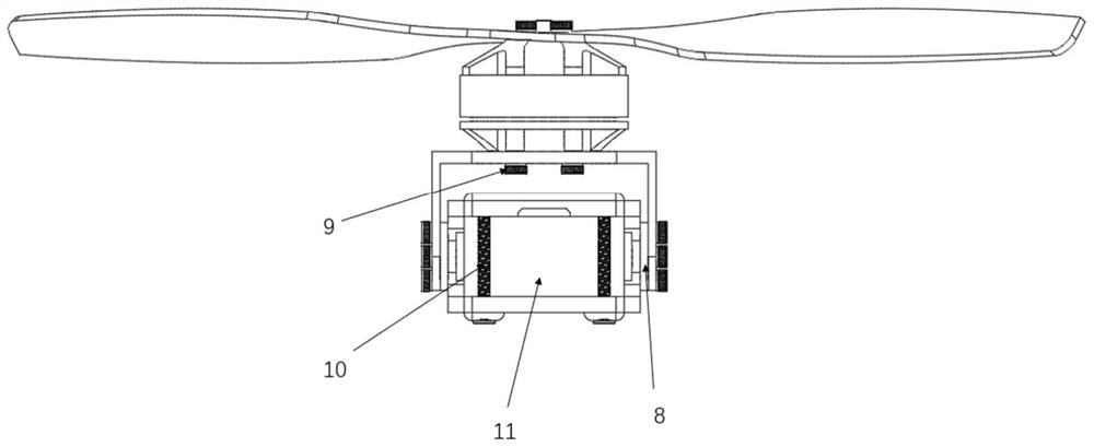
[0051] Among them, when the tilting part is in the first station (the structure at this time refers to figure 1 As shown), the motor unit drives the motor to work so that the screw rotates on the first rotation plane, and the first rotation plane is parallel to the plane where the wing is located;

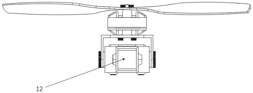
[0052] When the tilting part is in the second position (the structural reference at this time Figure 4 As shown), the motor unit drives the motor to work so that the pr...


PUM


Abstract

The invention discloses a tilting component of a tilting rotor unmanned aerial vehicle, which comprises a propeller, a motor base, a steering engine and a tilting base, wherein the propeller is connected with a direct-current brushless motor through propeller fixing screws; the direct-current brushless motor is arranged on the motor base through motor base fixing screws; the steering engine is fixed on a steering engine disc through steering engine fixing screws; the steering engine disc, the motor base and the tilting base are connected, and the tilting base is connected with the wings through tilting base fixing screws; the propeller is driven by the direct-current brushless motor controlled by a steering engine to be switched between a first rotating plane and a second rotating plane, and the first rotating plane is perpendicular to the second rotating plane. In addition, the invention further discloses a tiltable rotor unmanned aerial vehicle which comprises the tilting component of the tiltable rotor unmanned aerial vehicle. Moreover, the invention further discloses a using method of the tiltable rotor unmanned aerial vehicle.

Description

technical field [0001] The invention relates to the technical field of unmanned aerial vehicles, in particular to a tilting component of a tiltable rotor unmanned aerial vehicle, an unmanned aerial vehicle including the tilting component, and a use method. Background technique [0002] How to find a UAV that can take off and land vertically and has a long battery life has always been a pain point in the UAV market, and it is also a question that people have been thinking about. Driven by this demand, people have proposed many schemes from the aspects of power, structure, and aircraft layout. First of all, in terms of power, the concept of oil-powered multi-rotor or oil-electric hybrid multi-rotor has been proposed at home and abroad. The gasoline engine directly drives the rotor or the generator converts gasoline chemical energy into electrical energy for the rotor to improve the multi-rotor. Human-machine endurance time; secondly, in terms of structure, some people propose...

Claims


Application Information

Patent Timeline
Patent Type & Authority Applications(China)
IPC IPC(8): B64C27/28
CPCB64C27/28B64U30/10B64U10/25B64U30/20B64U50/19B64U10/10
Inventor 解忠良王雪瑞陈佳平刘生鹏冯学贵田文超周金柱高宏伟时婧蔡改改郝亮杨苾妍
Owner XIDIAN UNIV
Why Eureka
Try Eureka