Multi-layer multi-time continuous rolling ageing dyeing mechanism and method

A pressing and steaming technology, applied in continuous processing of textile materials, removal of liquid/gas/vapor with squeeze rollers, accessories of textile processing machines, etc. , reduce operating costs, improve the effect of dyeing depth

Pending Publication Date: 2020-10-16
李雅
View PDF7 Cites 3 Cited by
  • Summary
  • Abstract
  • Description
  • Claims
  • Application Information

AI Technical Summary

Problems solved by technology

[0005] The embodiment of the invention discloses a multi-layer and multiple continuous pressing and steaming dyeing mechanism and method, which are used to solve the technical problem that the amount of liquid in the cloth after pressing is relatively high in the existing pressing method for cloth dyeing

Method used


Image

  • Multi-layer multi-time continuous rolling ageing dyeing mechanism and method
  • Multi-layer multi-time continuous rolling ageing dyeing mechanism and method
  • Multi-layer multi-time continuous rolling ageing dyeing mechanism and method

Examples


Embodiment 1

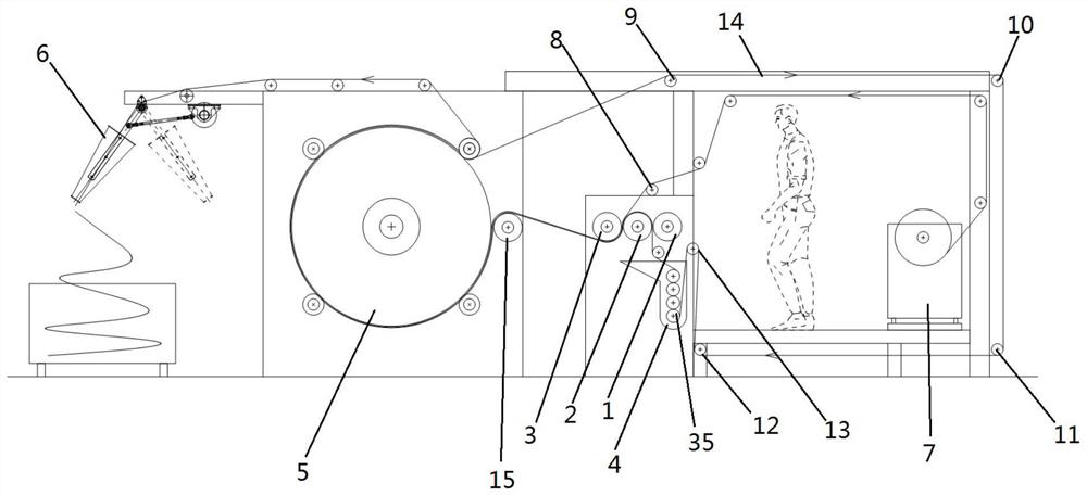
[0057] see figure 1 , a kind of multi-layer multiple continuous pressing and steaming dyeing mechanism provided in the present embodiment comprises:

[0058] Frame, cloth sending device 7 for sending cloth 14, rolling device 24, cloth guiding wheel device, first heating device 5 and finished product collecting device 6;

[0059] The bottom of the rolling device 24 is provided with a trough 4 for accommodating dye liquor or functional paint, and the first heating device 5 is arranged at the discharge end of the rolling device 24. The rolling device 24 includes at least the first roll 1, the second roll 2 and the third roll 3;

[0060] The cloth guide wheel device includes at least the first cloth guide wheel 8, the second cloth guide wheel 9, the third cloth guide wheel 10, the fourth cloth guide wheel 11, the fifth cloth guide wheel 12 and the sixth cloth guide wheel 13, the cloth 14 The moving track of the first cloth guide wheel 8, the second cloth guide wheel 9, the third...

Embodiment 2

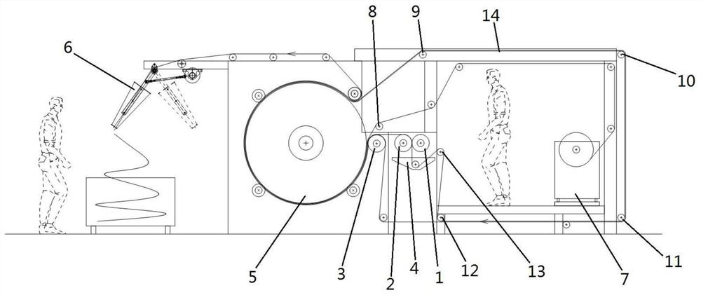
[0068] see figure 1 , the present embodiment increases the fourth roll 15 on the basis of the rolling device 24 in the first embodiment, specifically:

[0069] The rolling device 24 in this embodiment also includes a fourth roller 15;

[0070] The first roll 1, the second roll 2, and the third roll 3 are pressed against each other, and the fourth roll 15 is arranged between the third roll 3 and the first heating device 5, and is pressed against the first heating device 5;

[0071] The first cloth guide wheel 8 is arranged above the first roll 1 and the second roll 2, the first cloth guide wheel 8 guides the cloth 14 to enter between the second roll 2 and the third roll 3, and the second cloth guide Wheel 9, the third cloth guide wheel 10, the fourth cloth guide wheel 11 and the fifth cloth guide wheel 12 are sequentially arranged on the frame, and the second cloth guide wheel 9 guides the cloth coming out from the discharge end of the first heating device 5 14 is guided to t...

Embodiment 3

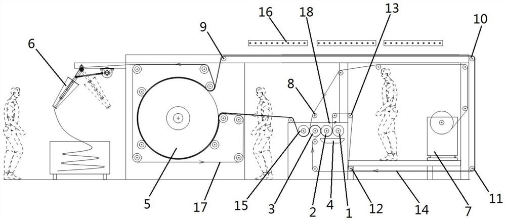
[0076] see image 3 , the present embodiment is on the basis of the trough 4 in the embodiment one, increasing the spraying device, specifically;

[0077] The spraying device in the present embodiment, the spraying device comprises spray pipe or shower head 18, pipeline, valve, pumping pump, filtering device, and spray pipe or shower head 18 is arranged on the top of rolling device 24, and toward the first roll 1 And the position between the second roll 2, nozzle or nozzle 18 is connected with hopper 4 by pipeline, filter device, valve and material pumping pump are all connected on the pipeline, nozzle or nozzle 18, hopper 4, pipeline, Valves, pumps, and filters form a cycle for liquid flow. It should be noted that, in this embodiment, the dye liquor in the trough 4 is pumped to the nozzle or nozzle 18 through the pipeline through the pumping pump, and the nozzle or nozzle installed between the first roller 1 and the second roller 2 18 can spray the dye liquor onto the surfa...


PUM


Abstract

The embodiment of the invention discloses a multi-layer multi-time continuous rolling ageing dyeing mechanism and a multi-layer multi-time continuous rolling ageing dyeing method, which are used for solving the technical problem that the liquid carrying amount of rolled cloth is too high in the existing rolling mode for cloth dyeing. The dyeing mechanism comprises a rolling device and a cloth guide wheel device. The rolling device at least comprises a first roller, a second roller and a third roller; the cloth guide wheel device at least comprises a first cloth guide wheel, a second cloth guide wheel, a third cloth guide wheel, a fourth cloth guide wheel, a fifth cloth guide wheel and a sixth cloth guide wheel; the moving track of the cloth is an irregular involute-shaped track; a cloth feeding device is located at the starting end of the involute-shaped track. A finished product collecting device is arranged at the tail end of the involute-shaped track, rolling points between the rollers are distributed on the involute-shaped track at intervals, the cloth guide wheels are distributed on the involute-shaped track at intervals, and the moving tracks of the cloth passing through a first heating device multiple times are arranged at intervals and are in a stacked shape.

Description

technical field [0001] The invention relates to the technical field of textile printing and dyeing, in particular to a pad dyeing and drying integrated dyeing mechanism and method. Background technique [0002] In the traditional heat-melt dyeing process of textiles, the fabric needs to be pad-coated with a dye solution, and then the cloth with the dye solution is heated and dried to sublimate and fix the color. There are many traditional pad-coating methods, such as uniform padding, heavy-duty padding, etc. They can evenly press the cloth soaked in dye solution well, but no matter what kind of rolling method, there is a problem that the amount of liquid in the cloth after rolling is too high, and the liquid in the cloth is high. In the subsequent drying process, more heat energy is needed to dry the moisture carried by the fabric, resulting in problems such as large equipment investment, large equipment footprint, high energy consumption, and high operating costs. Moreover,...

Claims


Application Information

Patent Timeline
Patent Type & Authority Applications(China)
IPC IPC(8): D06B21/00D06B1/02D06B3/18D06B15/02D06B23/02D06B23/04D06B23/22
CPCD06B21/00D06B1/02D06B3/18D06B23/22D06B23/04D06B23/023D06B15/02D06B2700/36
Inventor 不公告发明人
Owner 李雅
Why Eureka
Try Eureka