
Hydraulic balance reciprocating pump

A hydraulic balance and reciprocating pump technology, applied in the field of reciprocating pumps, can solve problems such as installation and maintenance difficulties, increased friction power consumption, and increased friction area

Pending Publication Date: 2020-10-20
NINGBO HELI MECHANICAL PUMP CO LTD
View PDF10 Cites 5 Cited by
  • Summary
  • Abstract
  • Description
  • Claims
  • Application Information

AI Technical Summary

Problems solved by technology

[0006] However, in the above-mentioned patents, no matter whether it adopts the method of adding a pressure balance cylinder to automatically adjust the pressure of the balance chamber or the method of designing the plunger with a variable cross-section structure, the hydraulic balance reciprocating pump always balances the hydraulic source on the hydraulic force of the plunger. The end part, that is, the plunger must be in the shape of a large and small head, and the annular area of ​​the large and small plunger is used as the balance point, which will inevitably lead to the doubling of the length of the plunger. The friction area is reduced, the assembly accuracy is reduced, and the friction power consumption is increased, the life is shortened, the cost is increased, and installation and maintenance are difficult

Method used


Image

  • Hydraulic balance reciprocating pump
  • Hydraulic balance reciprocating pump
  • Hydraulic balance reciprocating pump

Examples


Embodiment Construction

[0029] The present invention will be further described in detail below in conjunction with the accompanying drawings and embodiments.

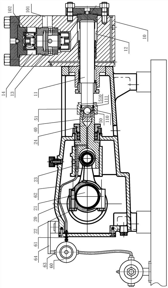
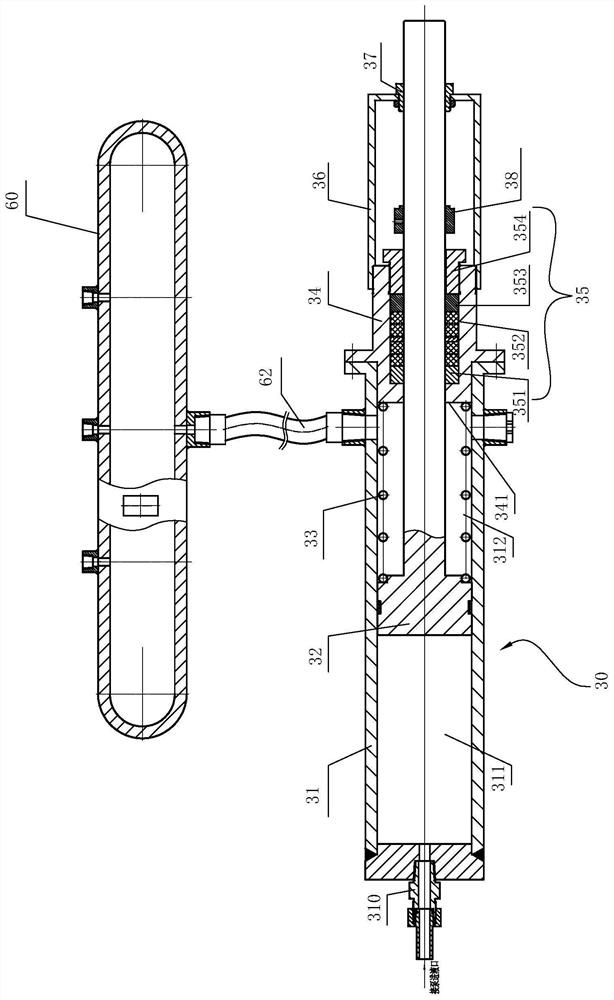
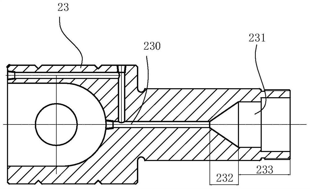
[0030] see Figure 1-Figure 6 , a hydraulically balanced reciprocating pump includes a fluid end, a power end and a synchronous isolation device 30 . The fluid end includes a pump body 10 , a plunger 11 , a plunger channel 12 , a valve group, a valve group channel 14 and corresponding packing seal components (not shown). The pump body 10 is provided with a liquid inlet 101 and a liquid discharge 102 . The plunger passage 12 communicates with the valve group passage, and the plunger 11 can reciprocate back and forth in the plunger passage 12 . The valve group of this embodiment can be selected as a combined valve 13 structure designed integrally with the liquid inlet valve and the liquid discharge valve, and the combined valve 13 is arranged in the valve group channel 14 . The power end includes a fuselage 20, a crankshaft 21 and a transmiss...


PUM


Abstract

The invention relates to a hydraulic balance reciprocating pump. The hydraulic balance reciprocating pump comprises a synchronous isolation device, an isolation sleeve with an inner cavity and a piston movably arranged in the inner cavity of the isolation sleeve, wherein the periphery of the piston is in sealing fit with the inner wall of the isolation sleeve and divides the inner cavity of the isolation sleeve into a first cavity and a second cavity, the first cavity communicates with a liquid inlet of a pump body, the second cavity is filled with hydraulic oil, an overflowing runner is arranged in a crosshead, a balance cavity is formed in the position, connected with the rear end of s plunger, of the front end of the crosshead, and the overflowing runner communicates with the second cavity so that the hydraulic oil in the second cavity can enter the balance cavity and act on the rear end of the plunger in a hydraulic mode. According to the hydraulic balance reciprocating pump, a pressure source of the hydraulic end compresses hydraulic oil through a piston in the isolation sleeve to transmit pressure to an overflowing runner and a balance cavity of the crosshead, then hydraulicforce acts on the plunger, the purpose of balancing plunger force is achieved, the motion stress face of the power end is promoted to enter lubricating oil, and the problem that dry grinding, heatingand burning loss occur due to the fact that lubricating oil cannot be supplied in an unbalanced mode is solved.

Description

technical field [0001] The invention relates to the technical field of reciprocating pumps, in particular to a hydraulically balanced reciprocating pump. Background technique [0002] A reciprocating plunger pump in a positive displacement pump includes a power end part and a liquid end part. The power end is crank, connecting rod and crosshead mechanism. The hydraulic end is the pump body, valve group, body plunger, packing, through the power source, motor, diesel engine, etc. The reciprocating plunger pump has a wide range of applications, such as oilfield water injection, oil transportation, and various high-pressure liquids in various industries and military fields. In recent years, with the change of water injection formation pressure in the secondary oil recovery of oilfields, especially the water injection wells in old oilfields often have different well pressures, and some wells in the batch of wells have the problem of rising pressure and no water injection. In t...

Claims


Application Information

Patent Timeline
IPC IPC(8): F04B9/02F04B53/16F04B53/14F04B53/10F04B53/22F04B1/00
CPCF04B1/00F04B9/02F04B53/109F04B53/14F04B53/143F04B53/144F04B53/16F04B53/22
Inventor 陈明海陈英峰陈英浩柯西
Owner NINGBO HELI MECHANICAL PUMP CO LTD
Learn More