
Gas thermal mass flow meter
A technology of mass flowmeter and flowmeter, which is applied in the direction of indirect mass flowmeter and mass flow measuring device, can solve the problems of measurement accuracy deviation, improve measurement accuracy, realize modularization and integration, eliminate turbulent flow and fluid inconsistency The effect of stabilizing fluctuations
Patent Information
- Authority / Receiving Office
- CN · China
- Current Assignee / Owner
- Publication Date
- 2020-10-20
Smart Images
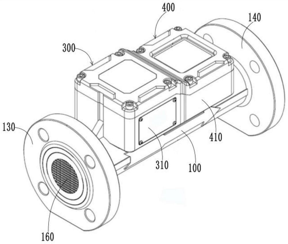
Figure 1 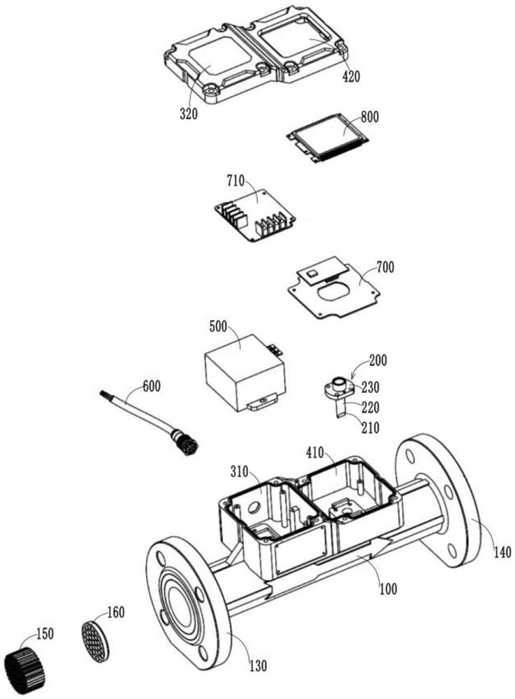
Figure 2 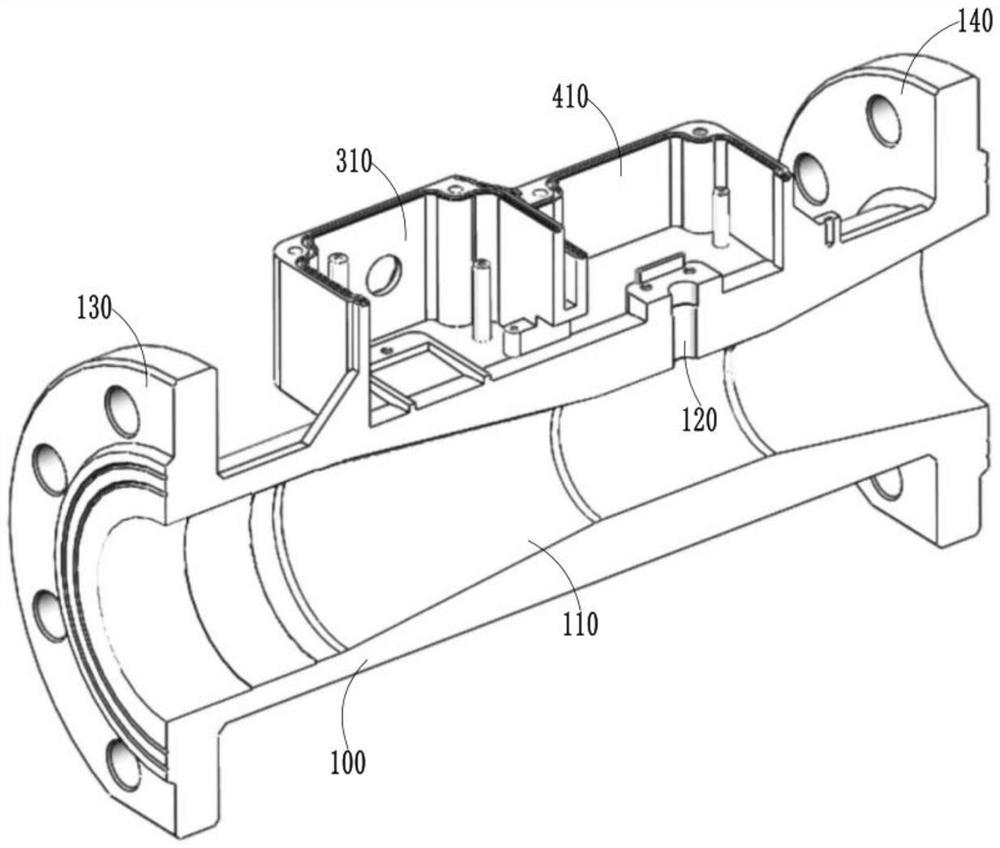
Figure 3
Abstract
Description
technical field
[0001] The invention relates to the field of gas flow measurement, in particular to a gas thermal mass flowmeter. Background technique
[0002] The advantage of the gas thermal mass flowmeter is that its measurement results are not affected by changes in ambient temperature and pressure, but when the mass flow is converted to standard volume flow measurement, if the calibration gas is inconsistent with the actual measurement gas, the measurement results will be affected by the gas. Effects of compositional changes. Therefore, when used for trade measurement purposes, it will conflict with existing measurement norms. For industrial gas measurement, a simple gas conversion factor can be used to obtain the repeatability required for measurement, but for the needs of trade measurement, the gas conversion factor cannot fully guarantee the accuracy required for measurement. The accuracy between the gas and the gas used is very necessary for its application in the...
Examples
Embodiment Construction
[0043] In order to make the above objects, features and advantages of the present invention more comprehensible, specific embodiments of the present invention will be described in detail below in conjunction with the accompanying drawings. It should be understood that the specific embodiments described here are only used to explain the present invention, not to limit the present invention.
[0044] figure 1 Schematic diagram of the structure of the gas thermal mass flowmeter provided in this embodiment, figure 2An exploded view of the structure of the gas thermal mass flowmeter provided in this embodiment, image 3 A schematic diagram of a half-section structure of the flowmeter main body 100 of the gas thermal mass flowmeter provided in this embodiment. Such as Figure 1 to Figure 3 As shown, this embodiment provides a gas thermal mass flowmeter, including a flowmeter body 100, a MEMS sensing element 200 and a control module 700, wherein the flowmeter body 100 has an airf...