Method for judging hook effect of homogeneous phase time-resolved fluorescence immunoassay

A technology of time-resolved fluorescence and hook effect, which is applied in the direction of material analysis, material analysis, fluorescence/phosphorescence, etc. through optical means, which can solve the problems of affecting detection throughput, consumption, and increased cost, and achieve high detection throughput. Effect

Active Publication Date: 2020-10-20
SUZHOU INST OF BIOMEDICAL ENG & TECH CHINESE ACADEMY OF SCI
View PDF15 Cites 4 Cited by
  • Summary
  • Abstract
  • Description
  • Claims
  • Application Information

AI Technical Summary

Problems solved by technology

Disadvantages: Adding target substances brings additional reagent consumption and increases costs; it can only be judged at the end of the reaction
At present, only Thermo Fisher's Kryptor series products are used clinically abroad, and its patent for judging the hook effect has not yet been retrieved. According to public info

Method used


Image

  • Method for judging hook effect of homogeneous phase time-resolved fluorescence immunoassay
  • Method for judging hook effect of homogeneous phase time-resolved fluorescence immunoassay
  • Method for judging hook effect of homogeneous phase time-resolved fluorescence immunoassay

Examples


Embodiment 1

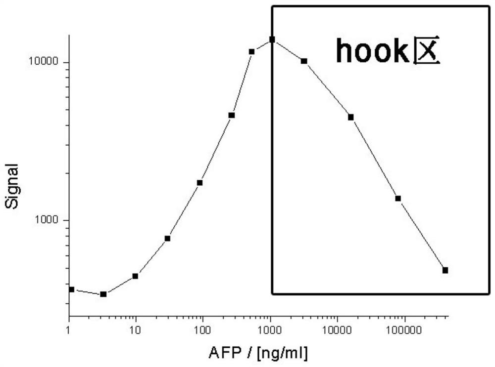
[0042] Example 1: Hook effect assay for AFP assay

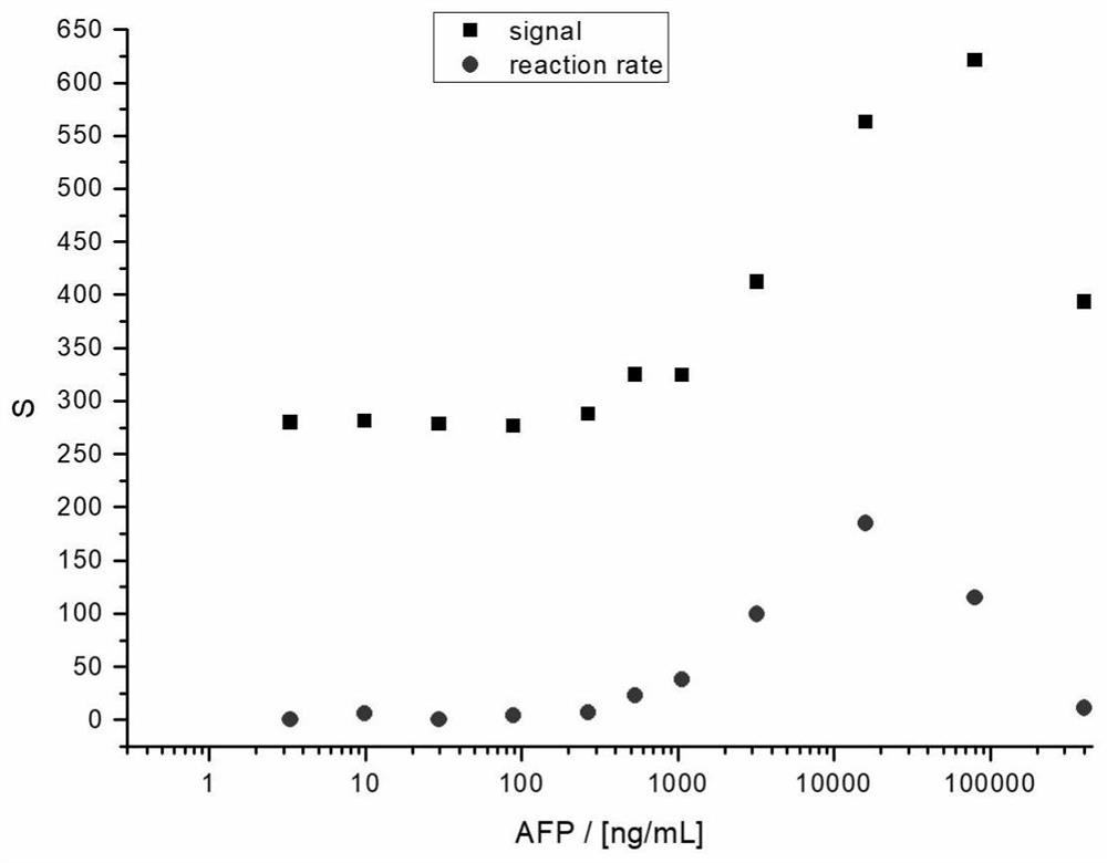
[0043] 2.3 Generate Calibration Curve

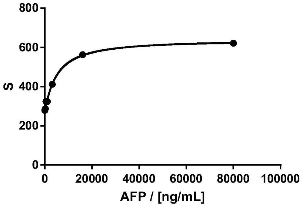
[0044] Detect the signal absolute value of a series of known concentration samples, and use the relationship between the measured signal absolute value and rate value and concentration to establish two calibration curves, within the range of positive correlation between concentration and signal (see figure 2 ), using four parameters for fitting to generate a calibration curve, the fitting curve of the relationship between the absolute value of the signal and the concentration is shown in image 3 , the fitting curve between the rate value and the concentration is shown in Figure 4 .

[0045] 2.4 Calculate the concentration of unknown samples using the calibration curve

[0046] Using the fitted four-parameter curve equation, the concentration value of the unknown sample can be calculated, and using two curves, two concentration values ​​can be calculated.

[0047] Concentr...

Embodiment 2

[0053] Example 2: Hook effect detection for AFP assays across different systems

[0054] 2.3 Generate Calibration Curve

[0055] The signal value and rate value measured between different systems (instruments) are different, Figure 5 Shows the systematic deviation of signal values ​​between the two instruments. Compared with Example 1, Example 2 introduces the 665 / 620nm measurement ratio of the blank sample as the background value, and the measurement system deviation of the calibration signal between different systems (instruments), the calculation method is as follows: divide the signal absolute value and the rate value With the background value, the relative signal absolute value (RS, relative signal) and the relative rate value (RRR, relative reaction rate) were respectively obtained. Under the same incubation conditions, the RS and RRR curves are only related to the degree of immune response, and have nothing to do with the deviation of the measurement system. Using th...


PUM


Abstract

The invention relates to a method for judging the hook effect of homogeneous phase time-resolved fluoroimmunoassay, which comprises the following steps: (1) measuring the fluorescence intensity of a fluorescence donor and a fluorescence receptor at two detection wavelengths under the same excitation wavelength, and taking the fluorescence intensity ratio of the two wavelengths as a signal value; (2) respectively establishing standard curves of the absolute value of the signal intensity, the rate value of the signal change and the sample concentration by measuring the signal values of at leasttwo moments in the reaction initial stage through linear fitting and four-parameter fitting; and (3) detecting the signal value of the unknown sample, and obtaining the concentration of the unknown sample according to the fluorescence intensity of the unknown sample through the standard curve, thereby avoiding the hook effect; and calculating the relative value of the relative signal intensity andthe signal change rate by utilizing the absolute value of the signal intensity and the ratio of the signal change rate value to the background signal, and realizing consistent results on different instruments. And concentration interpretation of more samples can be completed within set time, so that the system has higher detection flux.

Description

technical field [0001] The invention relates to a method for judging the hook effect of homogeneous time-resolved fluorescence immunoassay, belonging to the technical field of fluorescence immunoassay. Background technique [0002] The homogeneous time-resolved fluorescence immunoassay technique combines two techniques of fluorescence resonance energy transfer (FRET, Fluorescence Resonance Energy Transfer) and time-resolved fluorescence (TRF, Time Resolved Fluorescence). This technology utilizes chelate markers of rare earth elements with a crypt structure as fluorescent donors, and short-lived fluorescent molecules with good spectral overlap with the fluorescent donors as fluorescent acceptors. Fluorescence resonance energy transfer (FRET) occurs with the acceptor (second fluorescent label). In fluorescence resonance energy transfer, the lifetime of the acceptor to emit fluorescence is equal to the lifetime of the donor to emit fluorescence. Because the donor fluorescence...

Claims


Application Information

Patent Timeline
IPC IPC(8): G01N21/64G01N33/53G01N1/38
CPCG01N21/6408G01N21/6402G01N33/53G01N1/38
Inventor 刘涛
Owner SUZHOU INST OF BIOMEDICAL ENG & TECH CHINESE ACADEMY OF SCI
Why Eureka
Try Eureka