Control method of power converter circuit

A technology of power converter and control method, which is applied in the direction of high-efficiency power electronic conversion, circuit device, and regulation of electric variables, and can solve the problems of low impedance matching and low efficiency of multi-stage DC/DC circuits, etc.

Active Publication Date: 2021-01-22
爻新科技(上海)有限公司
View PDF3 Cites 0 Cited by
  • Summary
  • Abstract
  • Description
  • Claims
  • Application Information

AI Technical Summary

Problems solved by technology

[0006] In the power converter circuit, based on the dynamic compensation of series-series resonant network, the single-stage circuit topology of wireless power transmission with multiple control degrees of freedom can solve the problems of low efficiency, impedance matching and low power density of multi-stage DC / DC circuits. question

Method used


Image

  • Control method of power converter circuit
  • Control method of power converter circuit
  • Control method of power converter circuit

Examples


Embodiment Construction

[0069] Next, in order to explain this invention in detail, the form for implementing this invention is demonstrated based on drawing.

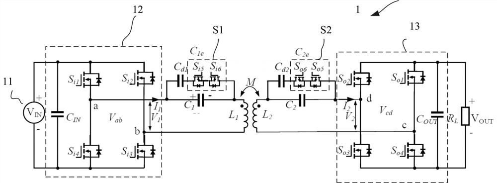
[0070] figure 1 is a diagram showing a circuit configuration of a power converter circuit according to the present invention. In the power converter circuit of the present invention, based on the magnetic resonance dynamic compensation, the variable capacitor in the series-series resonance compensation network dynamically modulates the equivalent resonance capacitance of the resonance compensation network, thereby realizing the dynamic compensation of the resonance circuit impedance. The parallel connection of the modulation capacitor and the resonant capacitor can effectively reduce the current flowing through the modulation switch tube and lower the requirements on device characteristics.

[0071] Such as figure 1 As shown, the power converter circuit 1 includes a DC power supply 11, an inverter 12, and a primary side variable capacitor C ...


PUM


Abstract

In the control method of the power converter circuit, a primary side independent control mode and a secondary side independent control mode are adopted to solve the problems of control stability and reliability caused by long time delay and the like of wireless communication in real-time information interaction, and avoid the problems of low electric energy conversion efficiency and low power density caused by a multi-stage circuit. For a primary side transmitting circuit, a phase shift angle alpha and a primary side dynamic compensation phase angle delta of an inverter are controlled, so thatpower transmission is adjusted, and the change of a coupling coefficient is adapted. For a secondary side receiving circuit, the phase shift angle beta of the rectifier and the phase difference phi between the input voltage and the input current of the rectifier are controlled, so that the equivalent load resistance is matched with the optimal load resistance, and the secondary side dynamic compensation phase angle rho is controlled, so that the reactance of the resonance network counteracts the equivalent load reactance, and the reactance of the secondary side impedance is zero. Through a primary side dynamic compensation phase angle delta and a secondary side dynamic compensation phase angle rho of the resonance network, primary side resonance capacitance and secondary side resonance capacitance are respectively adjusted, and disturbance of relative distance and offset between coils is counteracted.

Description

technical field [0001] The invention relates to power converter technology, in particular to a control method for a power converter circuit. Background technique [0002] With the wide application of low-power wireless power transmission technology such as mobile phone wireless charging, the application of wireless power transmission technology in medium and high power levels is also in-depth research and active attempts. However, the existing wireless power transmission technology still faces key technical bottlenecks such as low energy transmission efficiency, short distance, and poor offset resistance. [0003] In order to improve the energy transmission distance and efficiency, a technique of adding a resonant compensation network to the primary coil and the secondary coil in the power converter circuit to form a magnetic resonance is proposed. However, in the existing resonant compensation network, the compensation inductance in the composite compensation network LCC r...

Claims


Application Information

Patent Timeline
Patent Type & Authority Patents(China)
IPC IPC(8): H02J50/12H02M3/335
CPCH02M3/33576H02J50/12Y02B70/10
Inventor 李建廷
Owner 爻新科技(上海)有限公司
Why Eureka
Try Eureka