Sound field test analysis method and system based on machine vision and holographic method

A test analysis and machine vision technology, applied in radio wave measurement systems, instruments, measurement devices, etc., can solve the problems of limited application and difficult to obtain the local shape of the sound source surface.

Active Publication Date: 2020-10-23
SHANGHAI JIAO TONG UNIV
View PDF9 Cites 1 Cited by
  • Summary
  • Abstract
  • Description
  • Claims
  • Application Information

AI Technical Summary

Problems solved by technology

However, when this technology reconstructs the local vibration velocity of the irregular sound source surface, the local shape of the sound source surface is difficult to obtain, which limits the application of this method in engineering practice.

Method used


Image

  • Sound field test analysis method and system based on machine vision and holographic method
  • Sound field test analysis method and system based on machine vision and holographic method
  • Sound field test analysis method and system based on machine vision and holographic method

Examples


Embodiment Construction

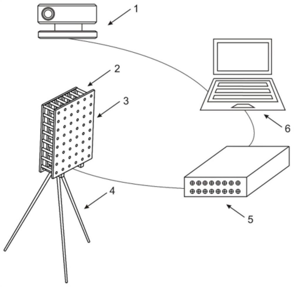
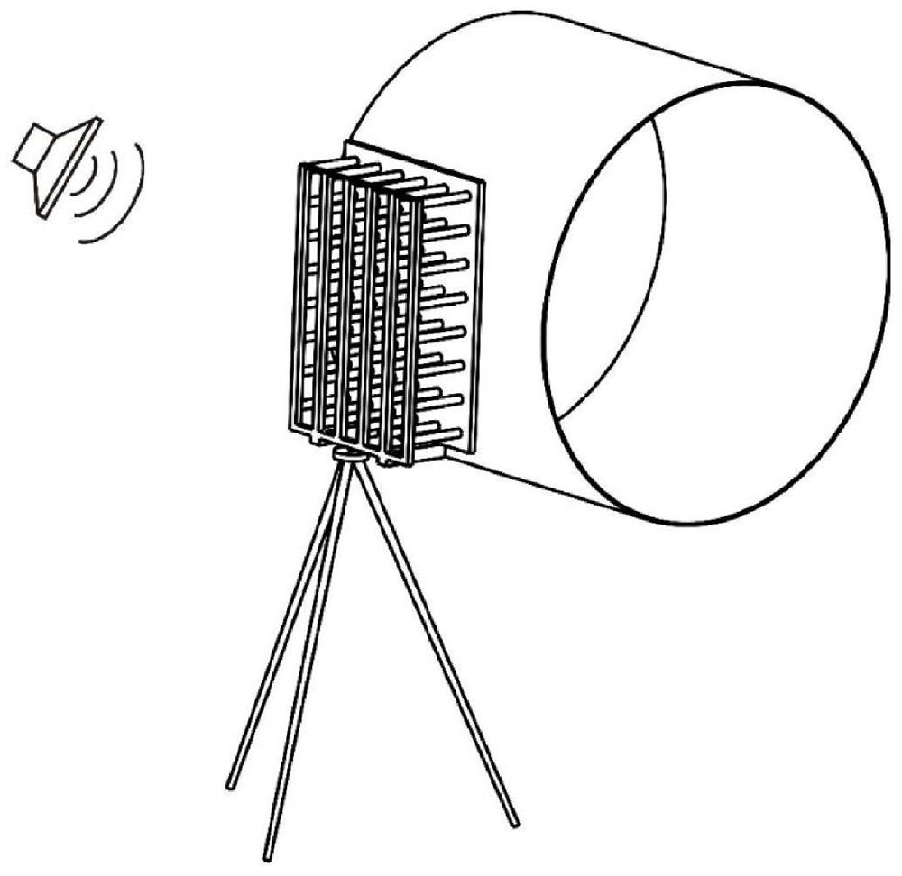
[0025] like figure 1 and figure 2 As shown, this embodiment relates to a sound field test and analysis system based on machine vision methods and holographic methods in a noisy environment, including: camera 1, microphone array 2, rigid acoustic shield 3, base 4, data acquisition module 5 and The camera 1 is directly connected to the sound source reconstruction module 6 .

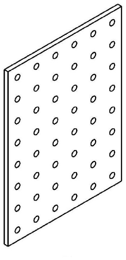
[0026] The microphone array 2 includes a plurality of microphones, the rigid acoustic shielding cover 3 is a plane, and a plurality of openings are discretely arranged on the plane, the number of the openings is consistent with the number of the microphones, and each opening corresponds to each microphone , the microphone is embedded in the corresponding opening of the rigid acoustic shield 3, and the microphone is arranged flush with the inner surface of the rigid acoustic shield 3 to ensure that the normal vibration velocity of the sound pressure collection point is zero.

[0027] The openings are pref...


PUM


Abstract

The invention discloses a sound field test analysis method and system based on machine vision and a holographic method. The method comprises steps of obtaining the regional grid information through pre-collection of the geometrical shape of a to-be-tested region, and building a boundary element model formed by an array and the to-be-tested region through combining with the position of a microphonearray; and performing sound pressure measurement by using a microphone array, calculating an impedance matrix between a holographic surface and a reconstruction surface in the boundary element modelby using a free field Green function, and reversely solving the normal vibration velocity of the reconstruction surface by using a regularization method to obtain the accurate position of the sound source. According to the method, the local surface vibration velocity of the irregular sound source can be reconstructed more conveniently in a noise environment.

Description

technical field [0001] The present invention relates to a technology in the field of noise processing, in particular to a sound field test and analysis method and system based on machine vision and holographic methods. Background technique [0002] The acoustic holography method in the non-free sound field environment can identify the noise source at the working site of mechanical equipment, which is very necessary for large-scale or mechanical equipment that cannot be moved into the anechoic room. The existing technology is based on the inverse block transfer function method of the rigid acoustic array for sound source reconstruction. This technology does not need to measure the particle velocity on the holographic surface or use a double-layer sound pressure measurement surface. It only needs to measure the sound pressure value, and then according to The impedance matrix is ​​calculated by the modal superposition method, and the surface vibration velocity of the sound sour...

Claims


Application Information

Patent Timeline
Patent Type & Authority Applications(China)
IPC IPC(8): G01S5/22
CPCG01S5/22Y02T90/00
Inventor 吴海军李豆蒋伟康
Owner SHANGHAI JIAO TONG UNIV
Why Eureka
Try Eureka