Conductive structure of isolation switch of direct-current cabinet of tracked (trackless) street car carriage

A technology of isolating switch and conductive structure, applied in the direction of electric switch, air switch parts, circuits, etc., can solve the problem of large dimensional tolerance of product assembly, increased contact resistance, and the operator cannot see the correct position of the moving knife component, etc. question

Pending Publication Date: 2020-10-23
金晓亮 +1
View PDF5 Cites 0 Cited by
  • Summary
  • Abstract
  • Description
  • Claims
  • Application Information

AI Technical Summary

Problems solved by technology

[0006] 1. The upper contact of the isolating switch knife is made of silver contacts, which are pressed to both ends of the input, and the output copper terminals usually use thin plate springs. The pressure is weak and insufficient, resulting in increased contact resistance and isolation. The temperature of the switch will increase during use
[0007] 2. Due to the manufacturing and material reasons of the moving knife assembly and the input and output copper terminals of the isolating switch, the current density in use is as high as 2.5-3A/mm2. When used in a closed electrical cabinet, the temperature will be further increased. raised
This will easily cause the heat of the switch to form a vicious circle, th

Method used


Image

  • Conductive structure of isolation switch of direct-current cabinet of tracked (trackless) street car carriage
  • Conductive structure of isolation switch of direct-current cabinet of tracked (trackless) street car carriage
  • Conductive structure of isolation switch of direct-current cabinet of tracked (trackless) street car carriage

Examples


Embodiment Construction

[0040] The present invention is specifically described below by the examples, the examples are only used to further illustrate the present invention, and can not be interpreted as limiting the protection scope of the present invention, some non-compliances made by those skilled in the art based on the content of the above-mentioned patent of the present invention Essential improvements and adjustments also belong to the protection scope of the present invention.

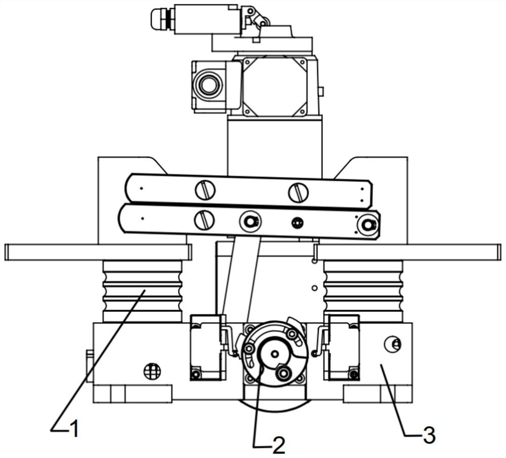
[0041] combine Figure 1 to Figure 6 .

[0042] Such as figure 1 As shown, the isolating switch among the present invention is mainly composed of conductive and insulating parts 1, a frame and a transmission part 2, and a drive and control part 3, three major parts. The components of the isolating switch will be described in detail below in conjunction with the accompanying drawings.

[0043] Conductive and insulating parts 1

[0044] Such as Figure 4 , four insulators 1005 are arranged on the above-mentioned a...


PUM


Abstract

The invention discloses a conductive structure of an isolation switch of a direct-current cabinet of a tracked (trackless) street car carriage. The conductive structure comprises a conductive and insulating part, a machine base and transmission part and a driving and control part. The conductive structure is a conductive part on insulators arranged at two ends of the base, the conductive part is composed of a bipolar double-phase incoming line, an output terminal and two groups of movable knife switches of eight copper bars connected with the output terminal, an alloy copper contact is arranged at the copper bar end, and the hardness of the contact is HRC 43-46 after the contact is subjected to heat treatment by a special process. And the movable knife switch and a copper terminal are pressed by a belleville spring. A nylon insulating cap is creatively mounted on a large-head screw outside the disc spring of the movable knife switch, so that 6000 A current can be insulated to the maximum extent. The switch with the conductive structure is stable in performance, safe and durable, can be used for a direct current cabinet of a tracked (trackless) street car, and can also meet the widerequirements of three-phase four-wire system alternating current power grids of traction power supply systems of subways, light rails, intercity and the like in urban rail transit.

Description

technical field [0001] The present invention relates to a conductive structure for isolating switches of DC cabinets with (without) railcars. The voltage levels used by the traction network are 750V and 1500V. The conductive structure has small resistance, low calorific value, safety and Stable and long service life. It has a wide range of applications and is suitable for the connection, isolation and conversion of strong currents and key components in medium, low-voltage, and high-current power transmission and distribution systems. It is especially suitable for rails, trolleybuses, and various Electric motor charging pile switches and box-type substations can also be used in tunnel cabinets, interval cabinets, power distribution cabinets, contact cabinets, especially in maintenance cabinets; at the same time, they can well meet the needs of subways, Traction power supply systems for light rail, intercity, etc., as well as extensive demands for three-phase four-wire AC power...

Claims


Application Information

Patent Timeline
IPC IPC(8): H01H31/02H01H1/025H01H1/50H01H1/58
CPCH01H31/02H01H31/023H01H31/026H01H1/025H01H1/50H01H1/58
Inventor 金晓亮徐忠芳
Owner 金晓亮
Why Eureka
Try Eureka