

Wireless charging system startup control method and device and wireless charging system
A power-on control and wireless charging technology, applied in circuit devices, battery circuit devices, current collectors, etc., can solve problems such as system power density and efficiency decline
- Summary
- Abstract
- Description
- Claims
- Application Information
AI Technical Summary
Problems solved by technology
Method used
Image

Examples
Embodiment 1
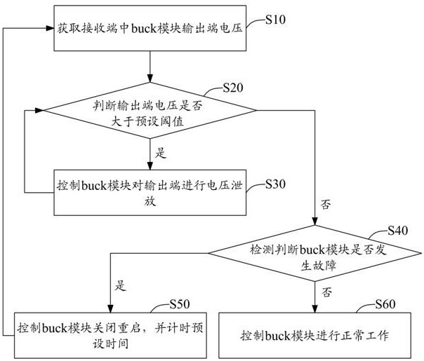
[0054] see figure 1 , is a schematic flow chart of the method for controlling the start-up of the wireless charging system provided by the first embodiment of the present invention. For the convenience of description, only the parts related to the embodiment of the present invention are shown. The method for controlling the start-up of the wireless charging system is applicable to the wireless charging system. Specifically in this embodiment, refer to Figure 5 As shown, its wireless charging system includes:
[0055] The transmitter 20 includes a first rectifier module 21, a high-frequency inverter module 22, a first control module 23, and a first wireless communication module 24 connected in sequence, and a transmitter coil 25 connected to the high-frequency inverter module 22;
[0056] And the receiving end 30 includes a receiving coil 31 , a second rectification module 32 , a buck module 33 , a second control module 34 , and a second wireless communication module 35 conn...
Embodiment 2
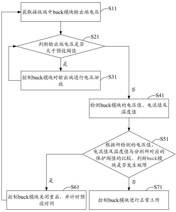
[0079] see figure 2 , is a schematic flow chart of a method for controlling the start-up of a wireless charging system provided by the second embodiment of the present invention. For the convenience of description, only the parts related to the embodiment of the present invention are shown. The method for controlling the start-up of the wireless charging system is applicable to wireless charging For the corresponding parts of the system, refer to the first embodiment above. Specifically, in this embodiment, the power-on control method of the wireless charging system includes:
[0080] Step S11, obtaining the output terminal voltage of the buck module in the receiving terminal;
[0081]Wherein, in the embodiment of the present invention, the specific steps for obtaining the voltage at the output terminal of the buck module at the receiving end refer to the description in the first embodiment above.
[0082] Step S21, judging whether the voltage at the output terminal is great...
Embodiment 3
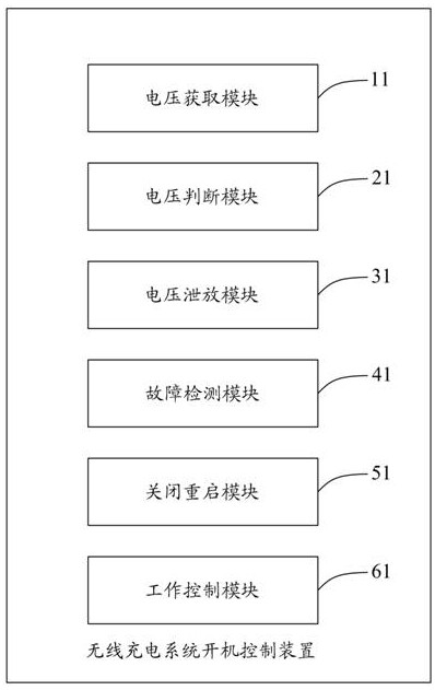
[0107] see image 3 , is a block diagram of a start-up control device for a wireless charging system provided by the third embodiment of the present invention. For convenience of description, only the parts related to the embodiment of the present invention are shown. The start-up control device for a wireless charging system includes:
[0108] A voltage acquisition module 11, configured to acquire the output terminal voltage of the buck module in the receiving end;
[0109] A voltage judging module 21, configured to judge whether the output terminal voltage is greater than a preset threshold, and the preset threshold is determined according to the output voltage level of the buck module;
[0110] The voltage discharge module 31 is used to control the buck module to discharge the voltage on the output terminal until the output terminal voltage is not greater than the preset threshold value when the voltage judgment module 21 judges that the output terminal voltage is greater t...
PUM
 Abstract
Description
Claims
Application Information