Electronic fishing tackle combination

An electronic fishing rig and electronic connector technology, which is applied to fishing lines, fishing accessories, fishing, etc., can solve the problems of difficult to observe the color change of the intelligent luminous drift, poor accuracy, and complex fishing rig composition.

Pending Publication Date: 2020-10-27
钟贤
View PDF8 Cites 0 Cited by
  • Summary
  • Abstract
  • Description
  • Claims
  • Application Information

AI Technical Summary

Problems solved by technology

The composition of the fishing group using intelligent luminous drift is: fishing line, 8-shaped ring, (4~6) space beans, lead seat wrapped with lead skin, drift seat, and intelligent luminous drift. The composition of the fishing group is relatively complicated and requires more With rich operating experience, fishing is more difficult and difficult for new fishermen to master; the tedious drift adjustment process is actually a process of counterweight adjustment. What is important is that a large number of discarded lead blocks produced during this process will cause environmental damage. Pollution; in the fishing process, when the target fish bites the hook, when the hook bite force is transmitted from the hook to the float, it needs to pass through a more complicated fishing group and a longer fishing line to transmit the signal to the intelligent luminous float, and the force transmission distance If it is too long, there will be a delay in time, and this delay will make the angler miss the best time to take up the rod; and when this type of fishing group is fishing in flowing waters, because the

Method used


Image

  • Electronic fishing tackle combination
  • Electronic fishing tackle combination
  • Electronic fishing tackle combination

Examples


Embodiment Construction

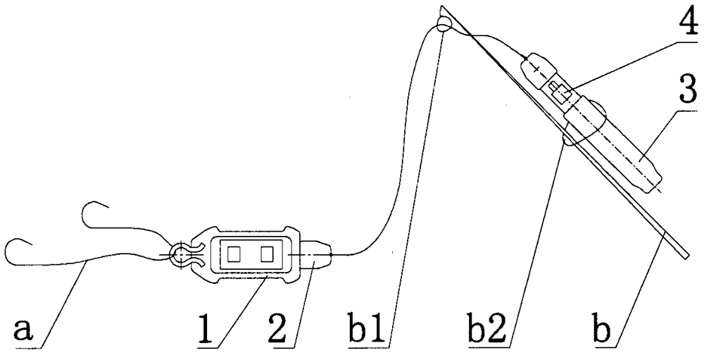
[0025] figure 1 As shown, it is a schematic diagram of the connection of an electronic fishing group. The electronic connector assembly 1 is used to connect the sub-line a, and the rod tip rope b1 on the fishing rod b is connected to the cable assembly 2, and the cable tie b2 is used to connect the The prompter assembly 3 bundles are placed on the position convenient for use on the fishing rod b, and the connection of the sub-line a, an electronic fishing group and the fishing rod b is completed.

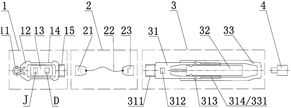
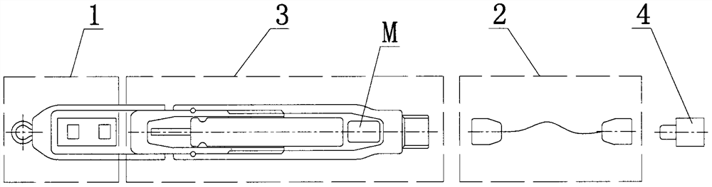
[0026] figure 2 Shown is a structural schematic diagram of an example of an electronic fishing rig, and its structure is mainly divided into four parts: electronic connector assembly 1, cable assembly 2, prompter assembly 3, buzzer with LED indicator 4.

[0027] The outside of the electronic connector assembly 1 is a housing 12 made of insulating material, one end of which is made of a metal connecting ring 11 that can be connected to the sub-wire, and the connecting ring 11 can ...


PUM


Abstract

The invention discloses an electronic fishing tackle combination, and relates to the field of fishing tackles for fishing. The electronic fishing tackle combination structurally comprises an electronic connector assembly, a cable assembly, a prompter assembly and a buzzer with an LED indicator lamp. A battery supplies power to a circuit board through a battery interface and a cable, and the circuit board starts to work; when a fish eats bait and pulls a sub-line, the sub-line enables the electronic connector assembly to move, an acceleration sensor module integrated on the circuit board immediately detects the motion state of the acceleration sensor module, acceleration data are transmitted to a program in a single-chip microcomputer module in real time for analysis and judgment, a signalis output according to the judgment result and transmitted to the prompter assembly through the cable to start the buzzer with the LED indicator lamp, and therefore fish information is rapidly fed back into sound and an indicator lamp signal to prompt a fisherman; and due to the fact that the electronic connector assembly sinks to the water bottom, the electronic fishing tackle combination cannotbe affected by water surface stormy waves. The electronic fishing tackle combination is simple, easy to operate, intelligent, high in precision, capable of saving energy, environmentally friendly andhigher in adaptability.

Description

technical field [0001] The invention relates to the field of fishing tackle used for fishing, in particular to an electronic fishing group. Background technique [0002] Fishing is a kind of recreational activity, and the existing intelligent fishing group has intelligent luminous drift (refer to the authorized announcement number: CN 205727729 U). It converts the hook biting signal into the color signal of the tail through the needle battery and circuit board built in the intelligent luminous drift, and then prompts the angler to judge the timing of the rod. Using the intelligent luminous drift at night makes the interpretation of the bait signal more difficult than the traditional one. Fishing becomes more accurate and easier. The composition of the fishing group using intelligent luminous drift is: fishing line, 8-shaped ring, (4~6) space beans, lead seat wrapped with lead skin, drift seat, and intelligent luminous drift. The composition of the fishing group is relativel...

Claims


Application Information

Patent Timeline
IPC IPC(8): A01K91/06A01K97/12
CPCA01K91/06A01K97/125
Inventor 钟贤
Owner 钟贤
Why Eureka
Try Eureka