
Hot-melt processing equipment for wear-resisting rubber gloves

A processing equipment and wear-resistant rubber technology, applied in the field of wear-resistant rubber gloves hot-melt processing equipment, can solve problems such as affecting normal use, scratches on the surface paint, easy to rust, etc., to achieve the effect of easy observation

Active Publication Date: 2020-10-27
汉洛科(安徽)医疗设备有限公司
View PDF5 Cites 0 Cited by
  • Summary
  • Abstract
  • Description
  • Claims
  • Application Information

AI Technical Summary

Problems solved by technology

The oil-water mixture goes to the oil-water separator, the oil-water layer is separated, the upper layer of gasoline is recovered, the lower part of the water is pumped to the cooling water tower for cooling, and then the gas gasoline in the distillation tower is cooled, and the latex in the distillation tower is sent to the latex mixing tank according to its own pressure. After preparation, the glove raw material latex is separated by a centrifuge, and then used after coloring and filtering. However, traditional sol tanks generally cannot directly observe the height of the liquid level, and it is also not very convenient to sample the real-time mixing degree of the raw materials. In addition, the traditional sol tank is generally fixed on the tank body with multiple bolts to fix the sealing cover on the tank body, which is very awkward when disassembling and assembling. In addition, when the traditional sol tank is hoisted, its rope can easily cause damage to the tank body , causing scratches on the surface paint, causing it to be prone to rust and other problems, affecting its normal use. In addition, the glass at the position of the observation tube of the traditional sol tank will be covered by the heat or raw materials in the tank, resulting in the inability to adjust the tank. in vivo observation

Method used


Image

  • Hot-melt processing equipment for wear-resisting rubber gloves
  • Hot-melt processing equipment for wear-resisting rubber gloves
  • Hot-melt processing equipment for wear-resisting rubber gloves

Examples


Embodiment Construction

[0029] In order to make the technical means, creative features, goals and effects achieved by the present invention easy to understand, the present invention will be further described below in conjunction with specific embodiments.

[0030] In the description of the present invention, it should be noted that the terms "upper", "lower", "inner", "outer", "front end", "rear end", "both ends", "one end", "another end" The orientation or positional relationship indicated by etc. is based on the orientation or positional relationship shown in the drawings, and is only for the convenience of describing the present invention and simplifying the description, rather than indicating or implying that the referred device or element must have a specific orientation, use a specific Azimuth configuration and operation, therefore, should not be construed as limiting the invention. In addition, the terms "first" and "second" are used for descriptive purposes only, and should not be understood ...


PUM


Abstract

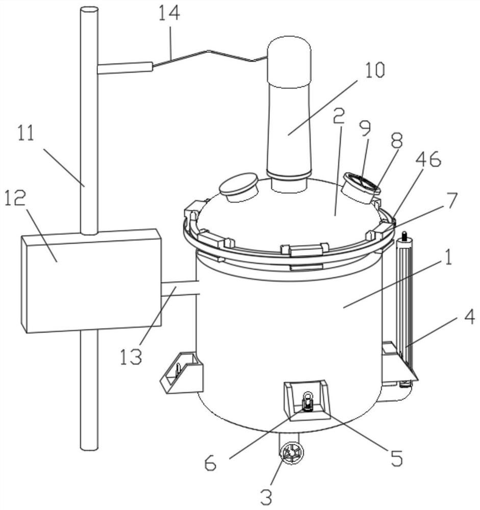
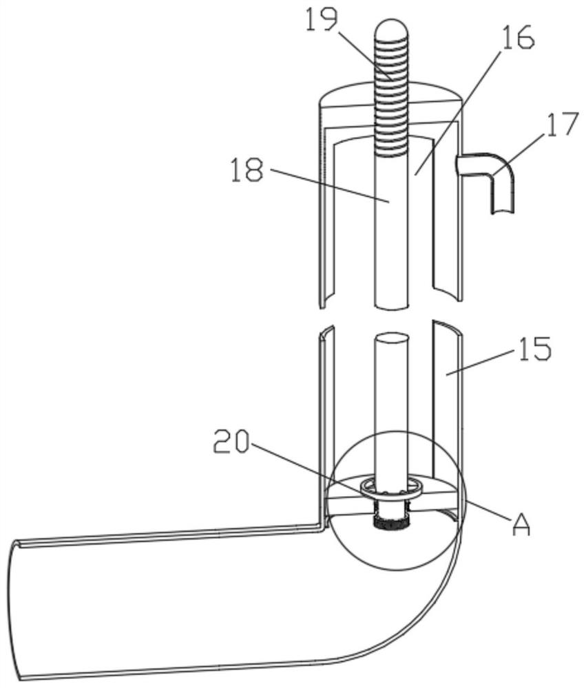
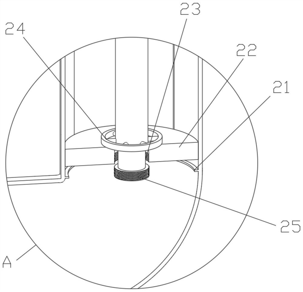
The invention discloses hot-melt processing equipment for wear-resisting rubber gloves. The hot-melt processing equipment comprises a tank body and a sealing cover, wherein the top of the tank body isprovided with a discharge mechanism; a sampling mechanism is arranged on the wall body below one side of the tank body; a plurality of support bases are further arranged on the outer wall below the tank body; connecting mechanisms are arranged in the support bases; the tank body and the sealing cover are fixedly connected through a plurality of fastening mechanisms; one side of the top of the sealing cover is provided with an observing tube; a wiping mechanism is arranged in the observing tube; a power mechanism is further arranged on the top of the sealing cover; and one side of the tank body is provided with a fixed rod. The sampling mechanism is arranged, so that raw material liquid level in the tank body can be observed real time, and therefore, adding amount of raw materials is conveniently regulated. An extracting sealing mechanism in the sampling structure can timely extract raw materials in a liquid column tube while needed. A fixing mechanism is arranged, so that the sealingcover can be quickly dismounted from the tank body.

Description

technical field [0001] The invention relates to the technical field of rubber glove processing equipment, in particular to a wear-resistant rubber glove hot-melt processing equipment. Background technique [0002] Rubber gloves are a type of gloves made of rubber sheets or films. They are divided into latex gloves and molded gloves according to rubber raw materials or manufacturing processes. Density 1.19), electrical insulating gloves are divided into high-voltage and low-voltage, high-voltage can be used below 6000 volts (test voltage is 12000 volts), low-voltage can be used below 1000 volts, and as the application environment continues to increase, its rubber Gloves also come in a variety of models for different environments, especially in the production process of a wear-resistant rubber glove, the rubber raw material is heated and mixed with other materials, and a sol is generally used The rubber is firstly sliced ​​by the rubber mixing machine, and then sent to the co...

Claims


Application Information

Patent Timeline
Patent Type & Authority Applications(China)
IPC IPC(8): B29B7/82B08B1/00B01J6/00B66C1/10G01N1/14
CPCB29B7/002B29B7/826B01J6/005G01N1/14B66C1/10G01N2001/1418B08B1/143B08B1/30
Inventor 熊正超
Owner 汉洛科(安徽)医疗设备有限公司
Learn More