
Efficient energy-saving fermentation treatment device

A treatment device, high-efficiency and energy-saving technology, applied in the field of fermentation, can solve the problems of high energy consumption, large floor space, poor fermentation performance, etc.

Pending Publication Date: 2020-10-27
JIANGXI SANYU ENVIRONMENTAL PROTECTION & ENERGY SAVING TECH CO LTD
View PDF9 Cites 6 Cited by
  • Summary
  • Abstract
  • Description
  • Claims
  • Application Information

AI Technical Summary

Problems solved by technology

Due to the long fermentation time of these fermentation methods, it generally takes 10-20 days, covers a large area, has low automation, and poor production environment
Limited to the disadvantages of conventional fermentation mentioned above, with the innovation of technology, the fermentation equipment is also constantly updated. In order to improve the fermentation efficiency in the existing fermentation equipment, it is usually necessary to heat the materials in the fermentation tank, and the heated materials will produce A large number of high-temperature gas-liquid mixtures are usually discharged directly in the prior art, thus wasting a lot of heat energy. If this part of heat energy can be recovered and reflowed to the fermenter to heat the material, the will greatly save energy
In addition, in the prior art, the energy saving of heating elements has not been well optimized, resulting in high energy consumption
[0003] Moreover, the temperature in the fermenter of the prior art cannot be well controlled, and the stability is poor, which never leads to poor fermentation performance

Method used


Image

  • Efficient energy-saving fermentation treatment device
  • Efficient energy-saving fermentation treatment device
  • Efficient energy-saving fermentation treatment device

Examples


Embodiment Construction

[0041] The present invention will be further described below in conjunction with the accompanying drawings and specific embodiments.

[0042] In the description of the present invention, it should be noted that unless otherwise specified and limited, the term "connection" should be understood in a broad sense, for example, it can be a fixed connection, a detachable connection, or an integral connection; It can be a mechanical connection or an electrical connection; it can be a direct connection or an indirect connection through an intermediary, and it can be the internal communication of two components. Those of ordinary skill in the art can understand the specific meanings of the above terms in the present invention in specific situations. In addition, the terms "first", "second", "third" and "fourth" are used for descriptive purposes only, for distinguishing from each other, and should not be understood as indicating or implying relative importance.

[0043] Such as figure...


PUM


Abstract

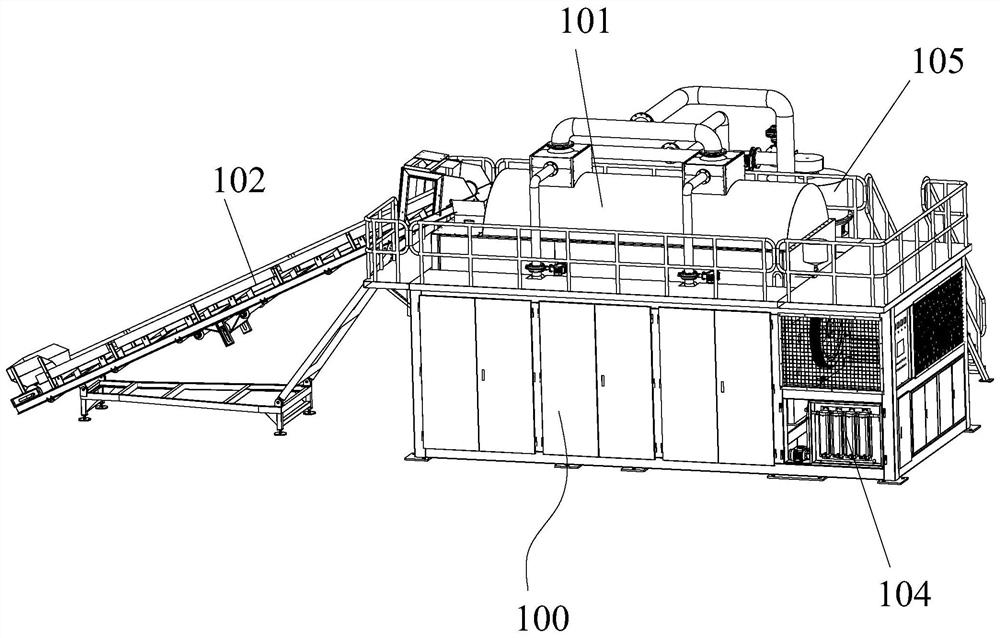
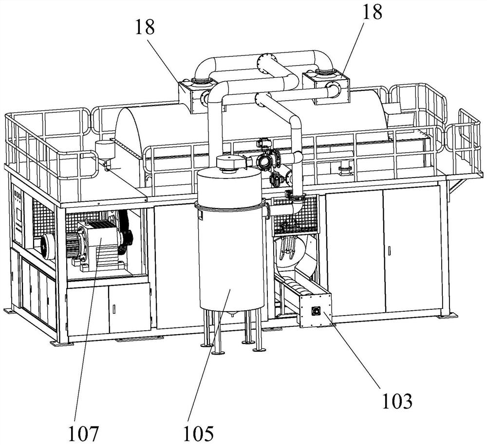
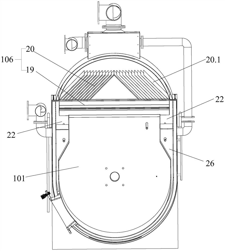
The invention discloses an efficient energy-saving fermentation treatment device, which comprises a rack, wherein a fermentation tank, a feeding mechanism, a discharging conveying mechanism and a heating device are arranged on the rack, the efficient energy-saving fermentation treatment device further comprises a gas-liquid separation device, the gas-liquid separation device comprises a shell, a high-temperature gas inlet, a hot air outlet, a fresh air inlet and a fresh air outlet are formed in the upper end of the shell, a gas-liquid separation assembly is arranged in the shell, the gas inletend of the gas-liquid separation assembly is communicated with the high-temperature gas inlet, the gas outlet end of the gas-liquid separation assembly is communicated with the hot air outlet, a water outlet is formed in the lower end of the shell, a first heater is arranged at the upper end of the gas-liquid separation assembly, the two ends of the first heater communicate with the fresh air inlet and the fresh air outlet correspondingly, and the fresh air outlet communicates with the inner cavity of the fermentation tank so as to achieve constant-temperature adjustment in the inner cavity of the fermentation tank. The efficient energy-saving fermentation treatment device disclosed by the invention can ensure good fermentation performance in the tank body, and can achieve the effect of effectively saving energy consumption.

Description

technical field [0001] The invention relates to the technical field of fermentation, in particular to a high-efficiency and energy-saving fermentation treatment device. Background technique [0002] The traditional organic fertilizer fermentation is usually strip-stack fermentation and trough fermentation. Due to the long fermentation time of these several fermentation methods, it generally takes 10-20 days, occupies a large area, has a low degree of automation, and has a poor production environment. Limited to the disadvantages of conventional fermentation mentioned above, with the innovation of technology, the fermentation equipment is also constantly updated. In order to improve the fermentation efficiency in the existing fermentation equipment, it is usually necessary to heat the materials in the fermentation tank, and the heated materials will produce A large number of high-temperature gas-liquid mixtures are usually discharged directly in the prior art, thus wasting a...

Claims


Application Information

Patent Timeline
IPC IPC(8): C05F17/90C05F17/964
CPCY02W30/40
Inventor 涂国强罗细苟
Owner JIANGXI SANYU ENVIRONMENTAL PROTECTION & ENERGY SAVING TECH CO LTD
Learn More