Positioning target, visual measurement system and method for acquiring flatness

A technology of visual measurement and positioning marks, applied in the field of visual measurement, can solve problems such as low efficiency, difficult digitization, and low measurement efficiency

Active Publication Date: 2020-10-27
菲烁易维(重庆)科技有限公司
View PDF8 Cites 4 Cited by
  • Summary
  • Abstract
  • Description
  • Claims
  • Application Information

AI Technical Summary

Problems solved by technology

Marking points are usually divided into passive marking points that rely on reflective light and active marking points that emit light. However, the accuracy of these two types of marking points cannot reach the micron level. It is necessary to expand the positioning accuracy to the micron level to achieve ultra-precise positioning. It has always been a technical problem in this field
[0003] According to the GB/T11337-2004 standard, the existing flatness measurement mainly includes direct measurement methods (gap method, indicator method, optical axis method, interference method, liquid level method) and indirect measurement methods (level method, self-calibration meter meth

Method used


Image

  • Positioning target, visual measurement system and method for acquiring flatness
  • Positioning target, visual measurement system and method for acquiring flatness
  • Positioning target, visual measurement system and method for acquiring flatness

Examples


Embodiment 1

[0049] This embodiment focuses on the description of the positioning target and its active light source.

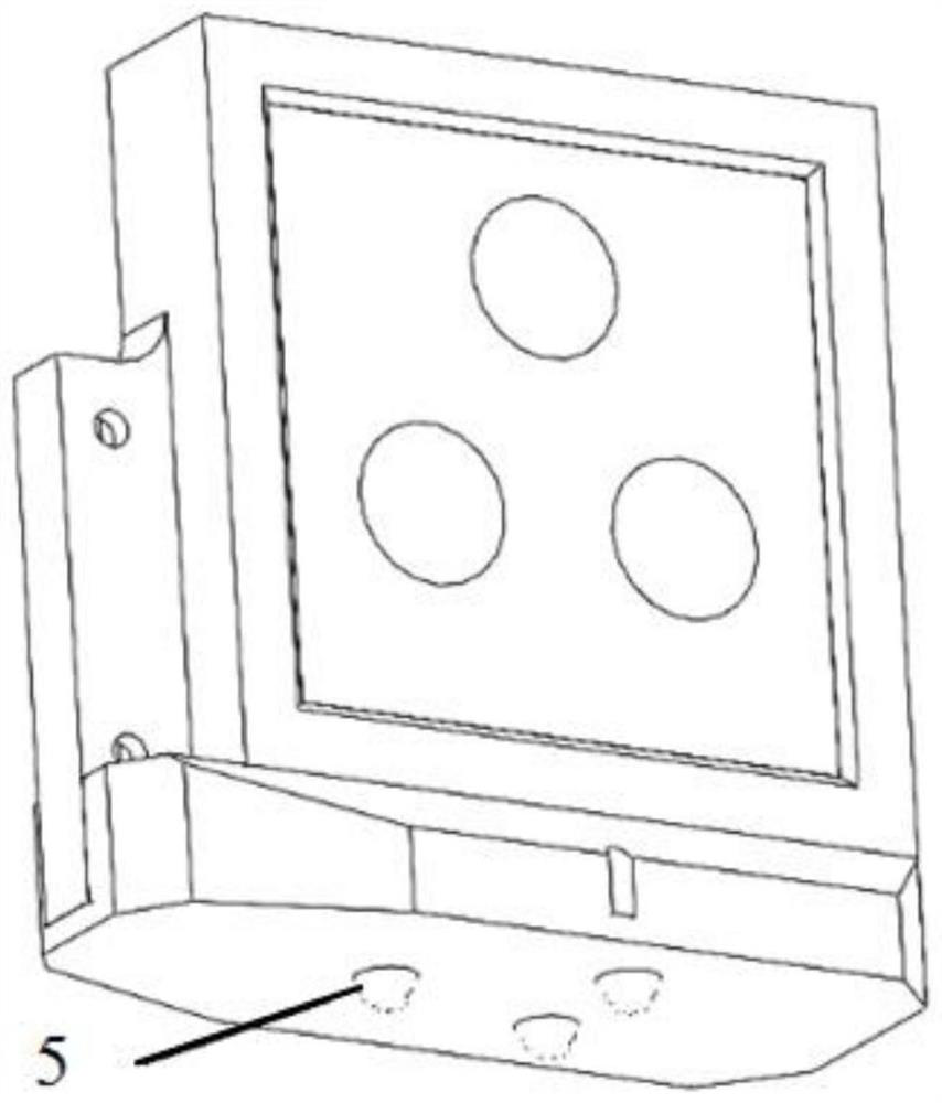
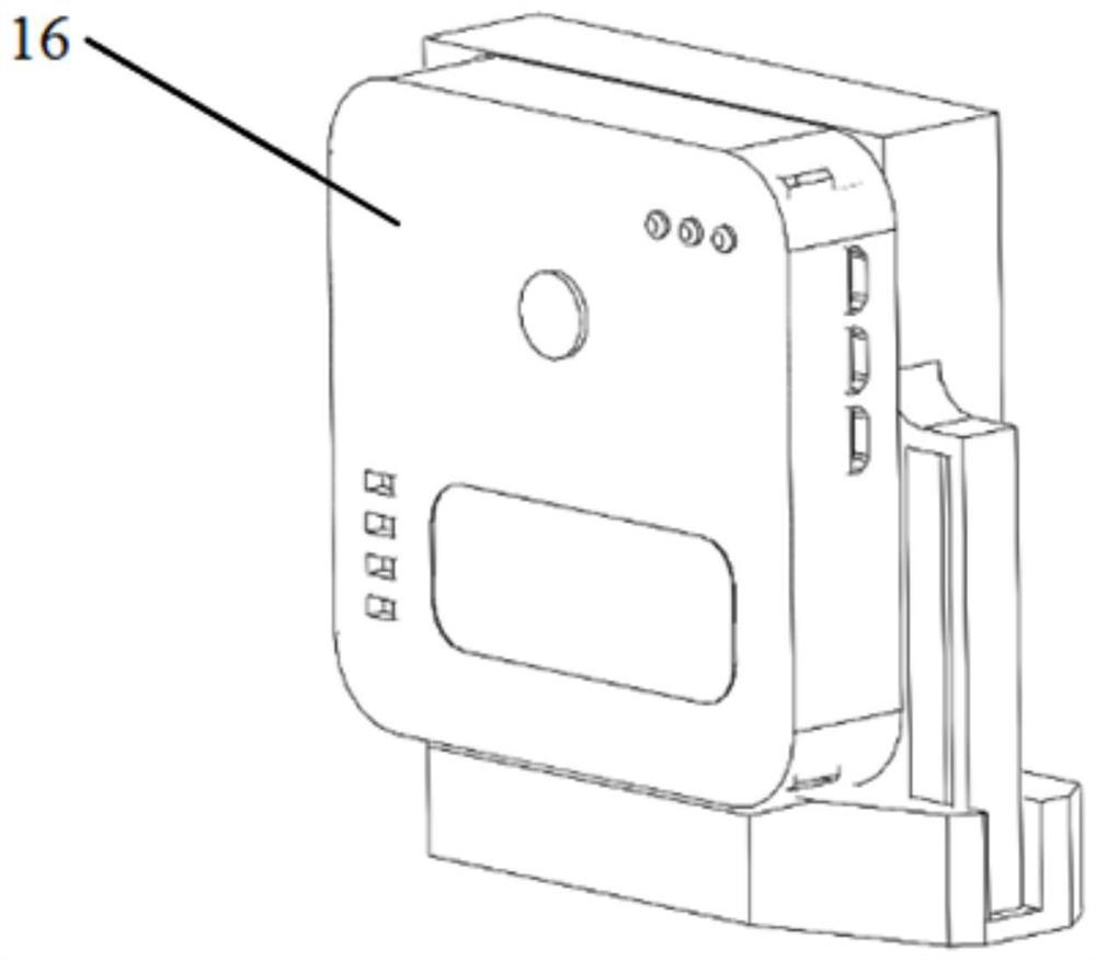
[0050] see figure 1 and figure 2 , a positioning target, including an active light source, at least three high-precision spheres 5 are arranged at the bottom of the active light source, and all the high-precision spheres 5 are not on the same straight line; the control board 16 is installed on the active light source. The measurement command is sent according to the set time; the sphericity error of the high-precision sphere 5 is less than 1um, and the diameter of the sphere is 2-10mm.

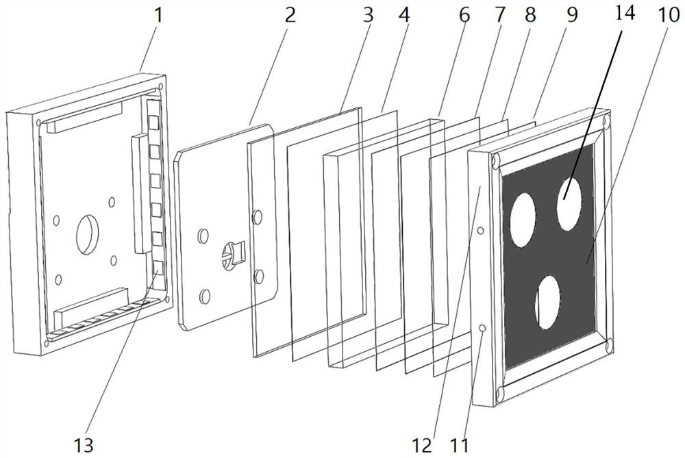
[0051] see image 3 and Figure 4 , the active light source includes a frame 1 and a light bar 13 arranged along the inner wall of the frame 1;

[0052] In the frame 1, an insulating board 2, a circuit board 3, a reflective film 4, a light guide plate 6, a light enhancement film 7, a light uniform film 8, a light shielding film 9, and a quartz glass sheet 10 are stacked in sequence, ...

Embodiment 2

[0064] see Figure 5 , a kind of visual measuring system, it comprises positioning target in embodiment 1 and is used for the camera 22 that matches with described positioning target, and camera is connected computer equipment (not shown), and described computer equipment comprises memory, processor and a program stored on a memory and operable on a processor, the processor implementing the following steps when executing the program:

[0065] Receive the measurement instruction sent by the control board 16 of the positioning target in real time, and execute capturing and recording the central coordinate P of the active light emitting light source of the positioning target; the central coordinate P of the active light emitting light source in the embodiment refers to A single center of the light part 14 or a certain geometric feature point of the geometric figure formed by the center of the circle, such as the geometric center;

[0066] Calculate the flatness of the surface co...

Embodiment 3

[0070] It should be noted that three high-precision spheres 5 that are not in the same straight line are fixed on the active light source. When the spheres are in point contact with the plane, under the force perpendicular to the plane, the surface to be tested is in contact with the three spheres respectively. , the relative positions of these three contact points remain unchanged. Assuming that the contact points between any plane S and three spheres are P1, P2, P3, and S is tangent to the three spheres at the same time, there is only one solution for P1, P2, P3. Therefore, relative to any plane S, P1, P2, P3 The distance is the same constant. Assuming that the center point of the active light source is O, since the active light source and the three high-precision spheres 5 are a rigid body, the distance h from point O to the plane S is constant. When the positioning target is on the measured plane When moving to measure different points, the distance h from point O to the ...


PUM


Abstract

The invention provides a positioning target, a visual measurement system and a method for acquiring flatness based on the positioning target and the visual measurement system. The positioning target comprises an active light-emitting lamp source, at least three high-precision spheres are arranged at the bottom of the lamp source and are not located on the same straight line, and a control mainboard is installed on the lamp source and used for sending a measurement instruction according to set time. The visual measurement system adopts the positioning target. The method for acquiringthe flatness comprises the following steps of fixing the visual measurement system, placing the positioning target at a to-be-measured part, and detecting the central coordinate of the positioning target throughthe visual measurement system,moving the positioning target to collect m points at the to-be-measured part and fitting to obtain a reference plane S',and continuously moving the positioning target toacquire the coordinate Pi of the ith point, and calculating the vertical distance from the coordinate Pi of the ith point to the virtual plane S'to serve as the plane deviation degree of the currentmeasurement point. The method has the advantages of high repeatability, high precision, high efficiency, interference resistance, light and small size, convenience in carrying and operation and the like.

Description

technical field [0001] The invention belongs to the technical field of visual measurement, and in particular relates to a positioning target, a visual measurement system and a method for obtaining flatness based on the positioning target and the visual measurement system. Background technique [0002] The marking point of visual measurement is a key technology in the field of machine vision. The marking point is installed on the measurement or tracking object, and the position and attitude of the object can be obtained quickly and accurately through image processing technology. Marking points are usually divided into passive marking points that rely on reflective light and active marking points that emit light. However, the accuracy of these two types of marking points cannot reach the micron level. It is necessary to expand the positioning accuracy to the micron level to achieve ultra-precise positioning. It has always been a technical problem faced by this area. [0003] ...

Claims


Application Information

Patent Timeline
IPC IPC(8): G01B11/30
CPCG01B11/30G01B11/002
Inventor 游四清黄科游晓龙白灵黄菊芳孔俊陈平平
Owner 菲烁易维(重庆)科技有限公司
Why Eureka
Try Eureka