
X-ray grating monochromator for high repetition frequency free electron laser

A high repetition frequency, X-ray technology, applied in the field of X-ray optical instruments, can solve the problems of grating affecting grating resolution, grating damage, inapplicability, etc.

Pending Publication Date: 2020-10-27
SHANGHAI ADVANCED RES INST CHINESE ACADEMY OF SCI
View PDF0 Cites 0 Cited by
  • Summary
  • Abstract
  • Description
  • Claims
  • Application Information

AI Technical Summary

Problems solved by technology

[0007] At present, the high repetition rate mode has become an important development direction in the field of free electron laser, but for the operation mode of high repetition frequency self-seeded free electron laser, since the grating in the above experiments cannot move laterally, as the repetition rate of the device increases, it will gradually Gratings cause destructive effects, resulting in a reduction in resolution, so the above-mentioned device cannot be used in the high repetition frequency self-seeding free electron laser operating mode, and is not applicable to the construction of 1MHz (10 MHz) in the world now. 6 Hz) This kind of high repetition rate free electron laser device
High repetition rate operation can have a destructive effect on the grating or affect the grating resolution, thereby affecting the actual operation of the self-seed free electron laser mode of operation

Method used


Image

  • X-ray grating monochromator for high repetition frequency free electron laser
  • X-ray grating monochromator for high repetition frequency free electron laser
  • X-ray grating monochromator for high repetition frequency free electron laser

Examples


Embodiment Construction

[0022] The present invention will be further described below in conjunction with the embodiments and accompanying drawings, but the protection scope of the present invention should not be limited thereby.

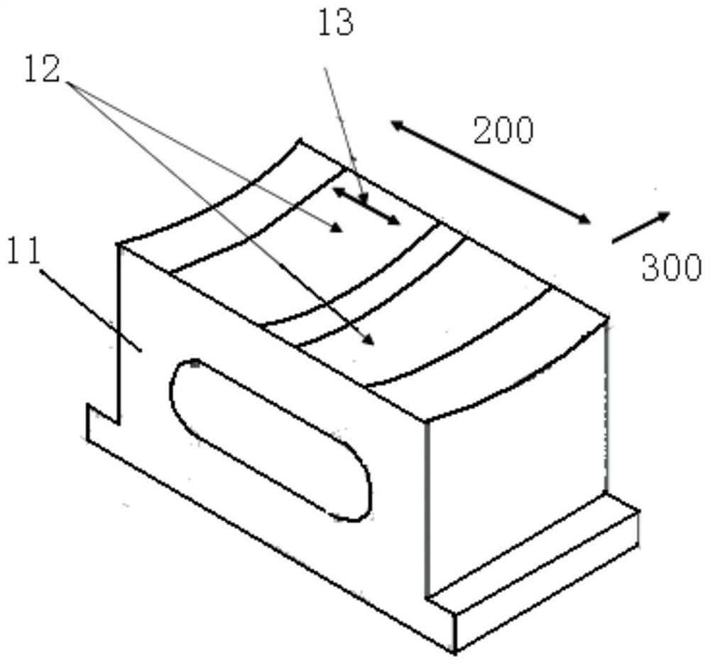
[0023] Such as figure 1 Shown is a connection diagram of an X-ray grating monochromator for high repetition frequency free electron laser according to an embodiment of the present invention. figure 2 is like figure 1 Schematic diagram of the structure of the X-ray grating monochromator for high repetition rate free electron laser shown. The X-ray grating monochromator is based on a movable grating, in this embodiment it is based on a movable cylindrical variable pitch grating.

[0024] Such as Figure 1-Figure 2 As shown, the X-ray grating monochromator for high repetition frequency free electron laser of the present invention is installed in a high energy free electron laser device, and it comprises: along the direction of the optical path of the incident light of a ho...


PUM


Abstract

The invention provides an X-ray grating monochromator for high repetition frequency free electron laser. The monochromator compriss a grating, a first reflecting mirror, a second reflecting mirror anda third reflecting mirror which are sequentially arranged in the direction of a light path of incident light and located on the same horizontal plane, wherein the grating and the third reflecting mirror are located on a first optical axis where the incident light is located, a connecting line of the first reflecting mirror and the second reflecting mirror is parallel to the incident direction ofthe incident light, incident light is high-repetition-frequency free electron laser, the position of the grating can be switched in the vertical direction, and therefore damage of the high-repetition-frequency free electron laser to the grating is effectively reduced. The monochromator is advantaged in that optical elements of the X-ray grating monochromator are all located on the same horizontalplane, the grating capable of switching the position in the vertical direction is adopted, free electron laser irradiates different positions of the grating, thermal deposition of an optical element is reduced, damage of the grating of the grating monochromator to the local position is reduced, and the grating monochromator can operate under a free electron laser device with higher repetition frequency.

Description

technical field [0001] The invention relates to the field of X-ray optical instruments, in particular to an X-ray grating monochromator for high repetition frequency free electron laser. Background technique [0002] X-ray grating is an important optical component, because it can disperse light in a certain wavelength range, it is widely used in spectrometers, optical monochromators and other instruments and equipment. Existing X-ray gratings are all coated with a single layer of optical material. Due to the single characteristics of a single optical material, this optical element often cannot guarantee resolution and service life at the same time. [0003] X-ray monochromator is a very important instrument and equipment, which is widely used in optical resolution and spectral purification of synchrotron radiation sources. Existing X-ray monochromators can be divided into soft X-ray monochromators based on gratings and hard X-ray monochromators based on masonry crystals acc...

Claims


Application Information

Patent Timeline
IPC IPC(8): G01N21/01G01N21/25G01N21/17
CPCG01N21/01G01N21/17G01N21/255G01N2021/0112
Inventor 张开庆冯超刘涛刘波赵振堂
Owner SHANGHAI ADVANCED RES INST CHINESE ACADEMY OF SCI
Learn More