Polarization beam splitter and forming method thereof

A polarizing beam splitter and polarized light technology, applied in the field of optics, can solve problems such as complex structure, inability to integrate on-chip, and large size

Pending Publication Date: 2020-10-27
SHANGHAI IND U TECH RES INST
View PDF4 Cites 3 Cited by
  • Summary
  • Abstract
  • Description
  • Claims
  • Application Information

AI Technical Summary

Problems solved by technology

[0005] The present invention provides a polarizing beam splitter and its forming method, which are used to solve the existing problems of the exis

Method used


Image

  • Polarization beam splitter and forming method thereof
  • Polarization beam splitter and forming method thereof
  • Polarization beam splitter and forming method thereof

Examples


Embodiment Construction

[0031] Specific implementations of the polarizing beam splitter and its forming method provided by the present invention will be described in detail below in conjunction with the accompanying drawings.

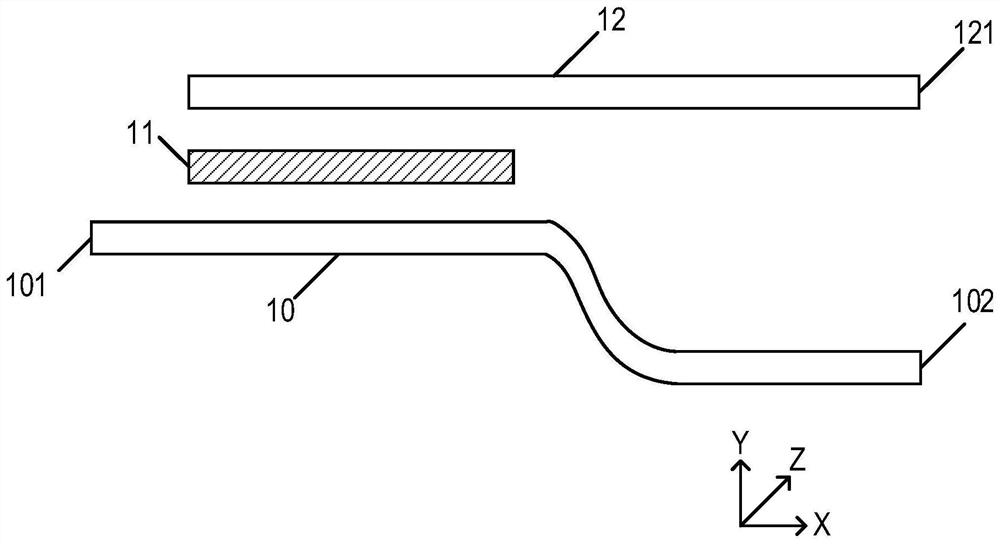
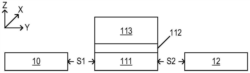
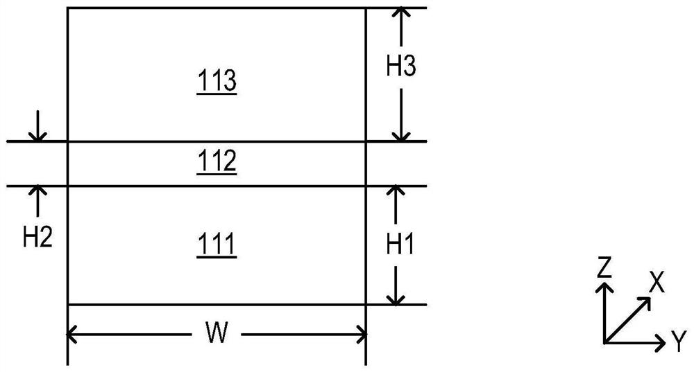
[0032] This specific embodiment provides a polarizing beam splitter, with figure 1 It is a schematic diagram of a top view structure of a polarization beam splitter in a specific embodiment of the present invention, with figure 2 is a schematic cross-sectional view of a polarizing beam splitter in a specific embodiment of the present invention. Such as figure 1 , figure 2 As shown, the polarization beam splitter provided in this specific embodiment includes:

[0033] Substrate;

[0034] A first waveguide 10, a slot waveguide 11, and a second waveguide 12 that are located on the surface of the substrate and extend along a first direction; the first waveguide 10, the slot waveguide 11, and the second waveguide 12 are in Arranged in parallel along a second direction perpen...


PUM

PropertyMeasurementUnit
Thicknessaaaaaaaaaa
Thicknessaaaaaaaaaa
Thicknessaaaaaaaaaa

Abstract

The invention relates to the technical field of optics, in particular to a polarization beam splitter and a forming method thereof. The polarization beam splitter includes a substrate, and a first waveguide, a slit waveguide and a second waveguide which are located on the surface of the substrate and extend in a first direction. The first waveguide, the slit waveguide and the second waveguide arearranged in parallel in a second direction perpendicular to the first direction, and the slit waveguide is located between the first waveguide and the second waveguide. The first direction is the propagation direction of light, and the first direction and the second direction are both parallel to the substrate. Transverse magnetic polarized light in the light can be coupled to the second waveguidefrom the first waveguide through the slit waveguide. According to the invention, separation of a TM polarization mode and a TE polarization mode in light is realized, and the polarization beam splitter has a plurality of potential applications in the aspects of polarization multiplexing, sensing and the like in the future.

Description

technical field [0001] The invention relates to the field of optical technology, in particular to a polarizing beam splitter and a forming method thereof. Background technique [0002] Polarization refers to the phenomenon that the vibration vector of a transverse wave (perpendicular to the propagation direction of the wave) is deviated in certain directions. In long-distance optical communication, the optical fiber is used as the transmission channel of the optical signal, and its ability to maintain polarization is poor, and the polarization state in it has a large randomness. In silicon-based optoelectronics, due to the low propagation loss of the TE (Transverse Electric, transverse electric) polarization state, the device is generally designed based on the TE polarization state, and the common silicon waveguide TE and TM (Transverse Magnetic, transverse The effective refractive index of the magnetic) polarization mode is quite different, and there will be no transformat...

Claims


Application Information

Patent Timeline
IPC IPC(8): G02B6/10G02B6/126G02B6/132G02B6/136G02B6/138
CPCG02B6/105G02B6/126G02B6/132G02B6/136G02B6/138
Inventor 汪大伟汪巍方青涂芝娟曾友宏蔡艳余明斌
Owner SHANGHAI IND U TECH RES INST
Why Eureka
Try Eureka